Configuration
3-1
Established digital outputs
may still be activated when
changing parameters or
calibrating. De-energize any
external equipment con-
trolled by the indicator’s
digital outputs while such
changes are being made.
3.
Configuration
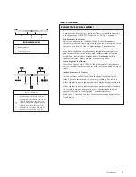
In this section:
■
Before You Begin
■
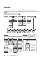
Moving Around the Menus
■
Setup Menu Chart
■
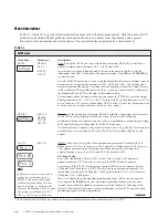
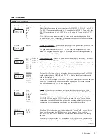
Setup Menu Descriptions
■
Serial Menu Chart
■
Serial Menu Descriptions
■
Calibration Menu Chart
■
Calibration Menu
Descriptions
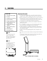
Before You Begin
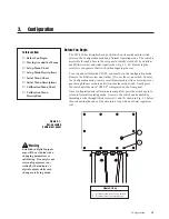
The CW-80 Checkweigher has a push-switch on its main board to switch
between the Configuration mode and Normal Operating mode. The switch is
accessible through a hole in the rear panel normally closed off by a drilled-
head fillister screw and water-tight washer (Fig. 3-1, #1). Removing the
screw lets you operate the switch without opening the case.
To set up and calibrate the CW-80, you must be in the Configuration mode.
Remove the fillister screw and washer (#1) over the set-up switch. To enter
the Configuration mode, insert a small diameter object like a screwdriver or
pen through the access hole until it touches the setup switch. Gently press
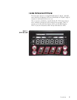
the switch until the word “SETUP” is displayed on the front panel.
Once configuration and calibration are completed, press the switch again to
return to Normal Operating mode. Access to the switch can be denied by
threading a wire through fillister screws (1) and (2) shown in Fig. 3-1 below,
then connecting the ends of the wire into a loop with an official regulatory
seal.
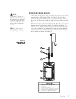
Figure 3-1.
Set-up switch
behind rear panel
Figure 3-1 Key
1 .. Fillister screw over set-up switch
2 .. Fillister screw for sealing case
1
2

