Maintenance and Troubleshooting
8-3
Main Board/Display Replacement
The steps below show you how to replace the CW-80 main board/display.
The procedure involves removing the power board and main board/display
to allow installation of the new board. Before you begin:
• Turn off the CW-80 power.
• Disconnect power cord from wall receptacle and battery backup.
• Establish a personal ground system, like a wrist strap, to prevent static
electricity discharges to a device.
• At the rear of the CW-80 head, remove the 10 phillips-head screws that
hold the back plate to the head.
Removal
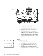
A. To remove the power board:
1.
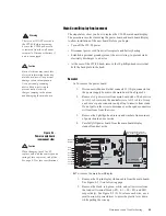
Disconnect ribbon cable that connects J1 (10-pin connector on
the power supply board) to the main board. See Figure 8-1.
2.
Remove AC power wires from main board studs. The hot wire
to AC-1 is brown, and the neutral wire to AC-2 is blue. Grasp
each wire’s spade connector and pull up to remove from studs.
Do not pull on the wires to disconnect, as the spade connectors
will tear loose from the wires.
3.
Remove the 4 phillips-head screws and washers from corners
of power board and set aside.
4.
Carefully lift power board from the main board/display
standoffs and set aside.
B. To remove the main board/display:
1.
Remove the 10-pin display ribbon cable from the main board.
See Figure 8-2 (1) on following page.
2.
Remove the black, red, green, white, and yellow wires from
the load cell terminal block (-EX, -S1, +S1, +EX, and SH1
respectively). See Figure 8-2 (2). To release each wire, use a
small narrow-tip screwdriver to press the plastic lever down
while pulling the wire up.
!
Warning
There is no ON/OFF switch on
the CW-80. Before beginning,
be sure the CW-80 power cord
is removed from the wall power
receptacle. Disconnect battery if
unit is so equipped.
!
Caution
Static electricity may cause loss
of stored information in the new
main board, as well as physical
damage to board components.
Use a personal grounding
device like a wrist strap to
prevent static electricity
charges jumping to the device
and damaging the main board.
Figure 8-1.
Power supply board
(component side)
!
Caution
When changing fuse F1 or F2,
replace only with the same type and
rating of fuse to prevent risk of fire.
See page 9-2 for fuse specifications.
J3
J2
Gnd
Under
Gnd
Accept
Over
Gnd
not used
1
8
AC-1
AC-2
GND
Battery -
B
2
3
4
5
6
7
not used
J1
Optional Relay
Sockets
➤
SPITZNAGEL
Nomex insulative strip over
AC voltage selection jumpers


