88
Counterpart Counting Scale Indicator
8.0
WLAN Installation Instructions
Note
Before installing this option, contact your IT administrator to obtain network communication protocol codes
and have a RS-232 communications cable or regular comm port cable available to run between your PC and
the indicator while installing and setting up the wireless network.
The optional Lantronix
®
WiPort
™
(WLAN — Wireless Local Area Network) wireless networking device can be
installed inside the
Counterpart
for real-time data transmission to warehouse management systems. The
Windows
®
-based configuration software, DeviceInstaller
™
is required for installation and setup and is available on
the CD that comes with the kit. The WLAN option can be factory installed or can be purchased separately and
installed on site.
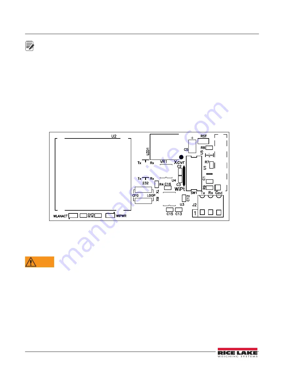
The wireless LAN option comes in a kit containing the following items:
•
Pluggable wireless board (PN 125787)
•
Antenna (PN 98357)
•
Standoffs (PN 95356)
•
CD containing Lantronix information (PN 72763)
Figure 8-1. WLAN Board
8.1
Enclosure Disassembly
The indicator enclosure must be opened to install the WLAN option card and antenna and to connect cables for the
installed option card.
WARNING
Before opening the unit, be sure the power cord is disconnected from the power outlet.
1. Disconnect power to the indicator.
2. Place the indicator face-down on an antistatic work mat.
3. Remove the screws that hold the backplate to the enclosure body and then lift the backplate away from the
enclosure and set it aside.
8.2
WLAN Card Installation
1. Refer to
CW-90/90X, 720i, 820i, iQUBE2, LaserLT WLAN Installation Instructions
PN 108680 included
with the WLAN option card for installation and configuration instructions.
2. This card assumes serial port 2 — the port 2 terminal on the Counterpart CPU board should not be
connected to any other device.


