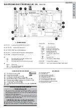
4 - CONNECTIONS
J1
=> EXP.12V
connector for EXPANDER card 12V (ACG5471)
J2
=> SEC.TRANSF.
Connector for the second transmitter
J3
=> BATTERYCHARGER Connector for battery charge card
J6
=> SEC.LOCK
Connector for the manual device safety release
J7
=> ENCODER
Connector for the Encoder
J9
LSO Limit switch contact, stopping the motor opening
COM.
Contacts common unit
LSC Limit switch connector, stopping the motor closing
J12
AERIAL
Radio antenna
COM
Contacts common unit
PHOT.1 NC Photocells contact (NC)
J13
=> MOTOR
Motor power supply
J14
STOP
Stop button contact (NC)
OPEN
Opening button contact (NA)
CLOSE
Closing button contact (NA)
K BUTT.
Single impulse contact (NA)
D+D-
12Vdc Accessories power supply
SIGNAL
Gate open - signal 3W max.
Buzzer
Blinker (max. 10W )
SIGN Warning LED - Battery discharged
J15
=> RADIO
Connector for radio receiver
LOW SPEED =>
Adjustment trimmer for the low speed.
BC07051
Pag. 17 di 28
OPERATING MICRO SWITCHES
DIP 1
Motor rotation control
(ON)
DIP 2
Timing
(ON)
DIP 3
Pause time before the automatic closing
(ON)
DIP 4
Jogging radio receiver
(OFF)
) - automatic
(ON)
DIP 5
Single impulse command (K BUTT) jogging
(OFF)
- automatic
(ON)
DIP 6
Photocells always active
(OFF)
- Photocells only when the gate closes
(ON)
DIP 7
Encode for the PLUS model (
ON-started)
DIP 8
Pre-blinking
(ON)
- Normal blinking
(OFF)
DIP 9
Pedestrian automatic closing operation
(ON-with EXPANDER)
DIP 10 FREE
LED SIGNALS
DL1 photocells contact (NC)
DL2 stop signal (NC)
DL3 closing limit switch contact (NC)
DL4 opening limit switch contact (NC)
DL5 programming started
DL6 gate on opening “OPEN” (green)
DL7 gate on closure “CLOSE” (red)
DL8 manual release safety device (NC)
DL9 Encoder operation check
IMPORTANT SAFETY INSTRUCTIONS
FOR THE INSTALLATION
1° - Install a thermal magnetic switch (omnipolar, with a minimum contact opening of 3
mm) before the control board, in case this is not provided with it. The switch shall be
guaranteed by a mark of compliance with international standards.
2° - As far as the cable section and the cable kind are concerned, RIB suggests to use
an NPI07VVF cable, with a minimum section of 1,5mm2, and to follow, In any case,
the IEC 364 standard and Installation regulations In force In your Country.
N.B.: THE SYSTEM MUST BE GROUNDED
Data described by this manual are only Indicative and RIB reserves to modify them at
any time.
Install the system complying with current standards and regulations.
E
N
G
L
I
S
H
ELECTRONIC BOARD KS 12V


