E
N
G
L
I
S
H
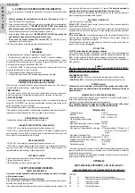
5 – CONTROL OF THE MOTOR ROTATION DIRECTION
This control is carried out to facilitate the installation of the system or any possible future
control.
1 -
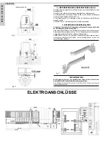
After you positioned the limit switch cams on the rack, (Fig.7 page 4)
, set Dip1 on
mode ON. The LED DL5 starts blinking.
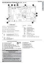
2 - Press and keep the button PROG. (the gate is now controlled with manned operation:
open-stop-close-stop-open-etc.).
THE GREEN LED DL6 “OPEN” turns on and the
gate opens and stops after having reached the limit switch cams.
If this does not
happen, release the button and invert the two cables of the motor.
3 - Press the button PROG. and keep it.
THE RED LED DL7 “CLOSE” turns on and the
gate closes and stops after it reaches the limit switch cams.
4 -
At the end of the control, position DIP1 on mode OFF
. The LED DL5 turns off,
signalling you exit from the control.
NB: The encoder and the photocells are not active during this control.
6 - TIMING
PROGRAMMING
The programming can be carried out regardless of the gate position.
1 - Position the micro switch Dip 2 on mode ON => The LED L1 emits short blinkings
2 - Push button PROG. => the gate closes. 2 seconds after the gate closed, it opens
automatically. When the opening cycle Is concluded, the gate stops. Wait as long as you
want the gate to remain open (excluded by DIP3 OFF)
3 - Push button PROG. to operate the gate closing (also the pause time count stops
before the automatic closing - max. 5 minutes).
4 - The gate stops when the closing cam is reached.
5 - Position Dip 2 back on mode OFF when the programming is concluded.
COMMAND ACCESSORIES OPERATION
OPENING BUTTON (with timer function) COM-OPEN
When the gate is standstill, the button controls the opening movement. If the button Is
operated while the gate Is closing, It opens the gate again.
TIMER FUNCTION
This function can be useful in rush hours, when vehicle traffic is slow (e.g. entry/exit of
workers, emergencies In residential or parking areas, and, temporary, for removals).
APPLICATION MODES
If you connect a switch and/or a daily/weekly timer (at place or in parallel to the opening
button N.O. “COM-OPEN”), you can open the automation and keep it open as long as the
switch is operated or the clock is activated.
When the automation is open, all operating functions are inhibited.
If the automatic closing Is selected, the automation Immediately closes when the switch Is
released or at the time previously set; If not, you need to use a command.
CLOSING BUTTON (COM-CLOSE)
It operates the closing movement when the gate is standstill.
JOGGING OPERATION BUTTON (COM-K BUTTON)
If DIP5 is OFF => It cyclically commands open-stop-close-stop-open-etc.
If DIP5 is ON => It opens the gate when this is closed. If this button Is operated while the
gate Is opening, It has no effect. It closes the gate If Is operated when this Is open and
opens the gate If Is operated while this Is closing.
RADIO TRANSMITTER
If DIP4 is OFF => It cyclically commands open-stop-close-stop-open-etc.
If DIP4 is ON => It opens the gate when this is closed. If It Is operated while the gate Is
opening, It has no effect. If It Is operated when the gate Is open, It closes the gate. If It Is
operated while the gate Is closing, it opens the gate again.
AUTOMATIC CLOSING
Pause times before the automatic closing of the gate are set with the timing procedure.
The max. pause time is 5 minutes.
DIP3 (ON started) can start or stop the pause time.
SAFETY ACCESSORIES OPERATION
SAFETY ENCODER (KPLUS)
It serves as a safety device both when the gate is opening and when it is closing,
with movement reversal.
DIP 7 (ON) enables the motor operation with encoder.
If the Encoder does not work (due to power supply failure, disconnected wires, broken or
defective disk), the gate Is not operated.
If the encoder operates the opening or the closing and than gives a reverse command, the
gate stops and than reverses Its movement for 1 second.
The buzzer is operated to
signal the alarm 5 minutes long and the blinker blinks one minute long.
During and after the 5 minutes when the buzzer alarms, you can make the gate work
again, just pressing the operating button you want.
PHOTOCELL 1 (COM-PHOT 1)
They work when Dip 6 is operated.
If Dip 6 is OFF
- When the gate is closed, It does not open if there is an obstacle within
the photocells range of action.
During operation, photocells work both when the gate opens (by starting the opening
movement after half a second), and when It closes (by starting the reverse movement
after one second).
If Dip 6 is on mode ON
- If an obstacle is present within the photocells range of action
when the gate is closed and Its opening Is commanded, the gate opens (during the
opening movement, photocells do not work).
Photocells work only during the gate closing (by starting the reverse motion after one
second, even if they are still engaged).
STOP BUTTON
The STOP button stops the gate during any operation.
If you push It when the gate Is totally open (or partly open, by using the pedestrian
command), this button temporary excludes the automatic closing (If selected by DIP3 and
DIP9). It Is than necessary to operate another command to make the gate close again.
The automatic closing function is enabled again the following opening cycle (If selected by
DIP3 and DIP9).
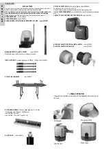
BLINKER
N.B.: This electric board can supply power only to BLINKERS WITH (ACG705
7
)
BLINKING CIRCUIT, with max. 10W lamps.
PRE-BLINKING FUNCTION:
- With DIP8 on ON
=> The motor, the blinker and the buzzer start at the same time.
- With DIP 8 on OFF
=> The blinker and the buzzer start 3 seconds before the motor.
BUZZER (Optional)
The buzzer emits an intermittent sound signal during opening and closing cycles.
When safety devices are operated (alarm), the intermittence frequency of this sound
signal increases.
WARNING LIGHT - GATE OPEN (COM-SIGNAL):
Its function Is to signal when the gate Is open, partly open or not totally closed anyway. It
turns off only when the gate Is totally closed.
This signal is not enabled during the programming procedures.
N.B.: If push button panels or lamps are overused, the logic system of the control
board will be compromised, resulting into a possible operation block.
TECHNICAL DATA
- Temperature range
0 ± 70°C
- Moisture
< 95% without capacitor
- Power supply voltage
230V~ or 120V~ ±10%
- 12Vac transformer power supply
- Frequency
50/60 HZ
- Max. power consumption of the card, loadless 120 mA
- Transient mains power drops
100mS
- Max. capacity of the warning light - gate open
3 W (corresponding to 1 3W lamp or to 5
LEDS with 2,2 kΩ resistance In
series)
- Max. load at the blinker output
10W 12Vdc
- Available current for photocells and accessories 1A 12Vdc
- Available current on the radio connector
200mA 12Vdc
- Battery power supply
10,2÷13Vdc
- Transformer capacity
180VA
- All inputs must be used as clean contacts, without being earthed, because the power
supply is generated in the card and is arranged so as to allow for double or reinforced
Insulation with respect to live parts.
All inputs are controlled by a programmed integrated circuit that carries out a self-control
cycle every time the gate is operated..
OPTIONALS
EXTRA FUNCTIONS
EXPANDER 12V
CARD (ACG5471)
!! FEED THE EXPANDER 12V CARD IN WHEN POWER IS NOT SUPPLIED !!
CAPTION
TR
=>
Adjustment trimmer for the courtesy light time
1-2
=>
12Vdc power supply for photocells, FOTOCOSTA units, etc….
3-4
=>
Traffic light 1 contact
5-6
=>
Traffic light 2 contact
7-8
=>
Courtesy light contact
Pag. 18 di 28


