15
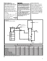
PROCEDURE FOR
CALCULATING THE TOTAL
EqUIVALENT LENGTH OF PIPE
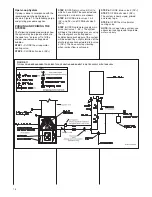
Given piping assembly as shown in
Figure 9 below, what is the total
equivalent length of the system?
First determine the total straight pipe
lengths; next refer to Table 1 to
determine the equivalent straight pipe
length for each fitting shown. Add
together the equivalent lengths of piping
and fittings.
(3/4”) Tubing 24 ft.
7 (3/4”) 90 deg. Elbows 7 (1.9) = 13.3 ft.
5 (3/4”) Side Port Tees 5 (3.8) = 19.0 ft.
1 (3/4”) Taco air separator = .3 ft.
2 (3/4”) Ball Valve 2 (.2) = .4 ft.
Total Equivalent Length . . . . . = 57 ft.
WHERE POSSIBLE THE LENGTH OF
PIPE SHOULD NOT EXCEED 100
FEET TOTAL EqUIVALENT LENGTH.
ANY PIPING RUNNING THROUGH
UNCONDITIONED SPACE MUST BE
INSULATED TO PREVENT HEAT
LOSS, AND POSSIBLE FREEZING OF
THE LINE.
STICkERS INDICATING DIRECTION
OF FLOW (WATER IN AND WATER
OUT) ARE LABELED ON THE
OUTSIDE OF THE CABINET. DO NOT
REVERSE THESE LINES, AS THIS
WILL CAUSE THE UNIT TO
MALFUNCTION.
Piping Configuration
When employing a Tankless Water
Heater in a hydronic system, the
system is considered an open-loop
system when configured to
simultaneously deliver both domestic
hot water and space heating. By
definition, if the circuit is sealed off
from the atmosphere at all locations
(as is true for most modern hydronic
systems), it is called a
closed-loop
system
. If the circuit is open to the
atmosphere at
any point
, it is called
an
open-loop system
.
NOTICE
FIGURE 10
EqUIVALENT LENGTH CALCULATION
Table 1 – Equivalent Length of Straight Pipe for Valves and Fittings (ft)
Diameter (in.)
0.375 0.5 0.75 1 1.25 1.5
Globe Valve 14.1 18.8 28.1 37.5 46.9 56.3
Angle Valve 6.3 8.3 12.5 16.7 20.8 25.0
Gate Valve 0.5 0.7 1.1 1.4 1.8 2.1
Ball Valve (BV) 0.1 0.1 0.2 0.3 0.3 0.4
90 Degree Standard Elbow 0.9 1.3 1.9 2.5 3.1 3.8
45 Degree Standard Elbow 0.5 0.7 1.0 1.3 1.7 2.0
Standard Tee with flow through run 0.6 0.8 1.3 1.7 2.1 2.5
Standard Tee with flow through branch 1.9 2.5 3.8 5.0 6.3 7.5
ST-A1242-09-00
*Optional for pump only and storage tank water heaters.
COLD
HOT
T
3
T
1
1-1/2 FT
BV
1
1 FT
T
4
EV
2
COLD
WATER
SUPPLY
T
2
T
5
EL
7
2 FT
1-1/2 FT
TEMPERED
WATER
AS
EL
5
1 FT
EL
6
2 FT
1 FT
4 FT
EL
4
4 FT
3 FT
EL
3
IN
1/2 FT
EL
2
EL
1
1 FT
OUT
AIR
HANDLER
Flow control Valve
(Storage tank and pumpless
applications only)
Pumpless only
WATER HEATER
Summary of Contents for RW1P
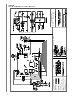
Page 29: ...29 FIGURE 21 ELECTRICAL WIRING DIAGRAM PSC MOTORS RW1P...
Page 32: ...32 FIGURE 24 ELECTRICAL WIRING DIAGRAM...
Page 33: ...33...
Page 34: ...34...
Page 35: ...35...
Page 36: ...36 CM 0617...


