


11
DUCTING
Proper air flow is required for the
correct operation of this air handler.
Too little air flow can cause erratic
operation and can damage the heat
exchanger. The duct system must
carry the correct amount of air for
heating and cooling if summer air
conditioning is used.
Size the ducts according to
acceptable industry standards and
methods. The total static pressure
drop of the air distribution system
should not exceed 0.8" w.c.
NOTE:
Return air grilles and warm air
registers must not be obstructed
IMPORTANT:
Some high efficiency
filters have a greater than normal
resistance to air flow. This can
adversely affect air handler operation.
BE SURE TO CHECk AIR FLOW.
IMPORTANT:
When using outside
air, design and adjust the system to
maintain a return air temperature
ABOVE 50° F during the heating
season.
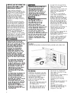
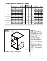
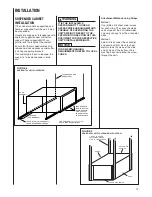
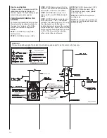
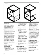
FIGURE 6
CUTOUT AND DRILL INFORMATION
UPFLOW ONLY
CUT OUT USING
EMBOSSED ANGLES
AS A GUIDE FOR THE
PROPER SIZE.
JACKET
*Solid metal bottom required if side duct penetration is used.
ST-A1242-04-X0
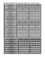
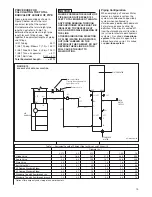
HYDRONIC AIR HANDLER HEATING PERFORMANCE
!"#$%&
'()*&%"#$
+()*$%&
,-$$.
/0#$%1"(&
2#"#34&
-%$225%$
63%&'()*
7$"#&
8"-"43#9
:1($#
;5#($#
<$(#"
:1($#
;5#($#
<$(#"
!"#
!#$
!!
%&#
!#"
'!
"()$!*
!'#
!!(
!*
*&(
!#+
'(
'!)*++
!*#
!""
!+
*&#
!!'
*!
'%)("+
!%#
!"$
"!
'&+
!!$
*,
*#)%$'
!(#
!'"
"+
'&'
!"#
%'
*%)*%*
!"#
$(
"*
*&#
!#*
'(
*,)#*#
!'#
!#!
"$
'&+
!!#
*"
%*)'##
!*#
!#%
'%
'&'
!!"
**
%,)%$+
!%#
!!%
'%
'&*
!!*
*(
%$)'*+
!(#
!"!
'$
'&'
!!+
%#
(*)'$+
!"#
!##
"#
*&+
$%
",
*,),((
!'#
!#'
",
*&"
!##
'"
%%),#'
!*#
!#%
'%
'&(
!#*
'(
(")'*!
!%#
!#+
*"
'&%
!!#
*"
,*)!*,
!(#
!#(
%*
'&#
!!*
*(
+#)$$,
!"#
$'
",
*&(
!##
'"
(")'#+
!'#
$+
'"
*&"
!#'
'%
(,)('%
!*#
!#!
'$
'&(
!#*
'(
($)$'(
!%#
!#'
*,
'&(
!!!
*'
+*)!'#
!(#
!#!
%$
'&'
!!+
%#
$,)%!*
63%&7"1.($%&=).$(
>?@=A
>%-BA
>31C&*C4CA
>8D=A
1234
#&%
!+##
(+&##
!"#$%&E$B-$%"#5%$
63%&E$B-$%"#5%$
>FDA
>FDA
(+&##
1234
#&%$
!"##
(+&##
!("%
#&%
1234
>+#5GH%A
(+&##
1234
#&%*
+##
*nOTE: Capacities are based on a constant inlet water temperature supplied by a tankless water heater and do not apply to storage tank applications.
Summary of Contents for RW1P
Page 29: ...29 FIGURE 21 ELECTRICAL WIRING DIAGRAM PSC MOTORS RW1P...
Page 32: ...32 FIGURE 24 ELECTRICAL WIRING DIAGRAM...
Page 33: ...33...
Page 34: ...34...
Page 35: ...35...
Page 36: ...36 CM 0617...


