26
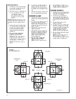
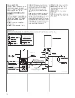
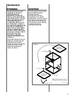
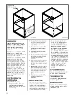
FIGURE 18
FILTER LOCATIONS
CUT OUT USING
EMBOSSED ANGLES
AS A GUIDE FOR THE
PROPER SIZE.
JACKET
the flue passageways, the vent
system and the main burners for
continued safe operation. Pay
particular attention to deterioration
from corrosion or other sources.
•
IMPORTANT:
It is recommended
that at the beginning and at
approximately half way through the
heating season, a visual inspection
be made of the main burner flames
for the desired flame appearance by
a qualified installer, service agency
or the gas supplier. If the flames are
distorted and/or there is evidence of
back pressure, check the vent and
inlet air system for blockage. If there
is carbon and scale in the heat
exchanger tubes, the heat
exchanger assembly should be
replaced.
REPLACEMENT PARTS
See sheet enclosed with air handler
for replacement part information.
TROUBLESHOOTING
Refer to Figure 18 for determining
cause of unit problems.
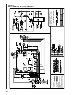
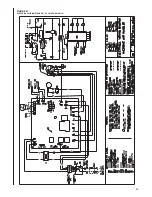
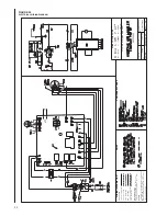
WIRING DIAGRAMS
Figures 19 through 22 are complete
wiring diagrams for the air handler
and power sources.
LUBRICATION
IMPORTANT: DO NOT
attempt to
lubricate the bearings on the blower
motor or the induced draft blower
motor. Addition of lubricants can
reduce the motor life and void the
warranty.
The blower motor and induced draft
blower motor are permanently
lubricated by the manufacturer and do
not require further attention.
The blower motor and induced draft
blower motor must be cleaned
periodically by a qualified installer,
service agency, or the gas supplier to
prevent the possibility of overheating
due to an accumulation of dust and
dirt on the windings or on the motor
exterior. And, as suggested
elsewhere in these instructions, the
air filters should be kept clean. Dirty
filters can restrict airflow. The motor
depends upon sufficient air flowing
across and through it to keep from
overheating.
SYSTEM OPERATION
INFORMATION
Advise The Customer
1. keep the air filters clean. The
heating system will operate
better, more efficiently and more
economically.
2. Arrange the furniture and drapes
so that the supply air registers
and the return air grilles are
unobstructed.
3. Close doors and windows. This
will reduce the heating load on
the system.
4. Avoid excessive use of kitchen
exhaust fans.
5. Do not permit the heat generated
by television, lamps or radios to
influence the thermostat
operation.
6. Except for the mounting platform,
keep all combustible articles 3
feet from the air handler and vent
system.
7.
IMPORTANT:
Replace all blower
doors and compartment covers
after servicing the air handler. Do
not operate the unit without all
panels and doors securely in
place.
8. Explain proper operation of the
system with constant air
circulation.
ANNUAL INSPECTION
• The air handler should operate for
many years without excessive scale
build-up in the flue passageways.
However, it is recommended that a
qualified installer, service agency, or
the gas supplier annually inspect
ST-A1242-04-X0
ST-A1242-07-X0
Summary of Contents for RW1P
Page 29: ...29 FIGURE 21 ELECTRICAL WIRING DIAGRAM PSC MOTORS RW1P...
Page 32: ...32 FIGURE 24 ELECTRICAL WIRING DIAGRAM...
Page 33: ...33...
Page 34: ...34...
Page 35: ...35...
Page 36: ...36 CM 0617...

