Installation manual
Daikin LMS
English
LMSEY1A09AVM01LMSEY1A13AVM01
LMSEY2A19AYE01LMSEY2A25AYE01
Page 1: ...Installation manual Daikin LMS English Installation manual Daikin LMS LMSEY1A09AVM01 LMSEY1A13AVM01 LMSEY2A19AYE01 LMSEY2A25AYE01...
Page 2: ...le units 25 6 6 About the alarms 26 7 Commissioning 26 8 Hand over to the user 27 9 Disposal 27 10 Technical data 27 10 1 Wiring diagram 27 10 2 Piping diagram 29 10 3 Weight 29 11 Glossary 29 1 About...
Page 3: ...could result in electrical shock short circuit leaks fire or other damage to the equipment ONLY use accessories optional equipment and spare parts made or approved by Daikin CAUTION Wear adequate per...
Page 4: ...bles and make sure they do NOT come in contact with the piping and sharp edges Make sure no external pressure is applied to the terminal connections Make sure to install earth wiring Do NOT earth the...
Page 5: ...efrigerating appliances and ice makers with an incorporated or remote refrigerant unit or motor compressor EN 12100 Risk assessment Directive and regulations 2006 42 CE EN ISO 13857 2020 Safety Distan...
Page 6: ...packaging bags so that nobody especially NOT children can play with them Possible consequence suffocation h i d b b Cardboard pillars d Pallet h Screws i Protection cover blue color 5 Remove the prote...
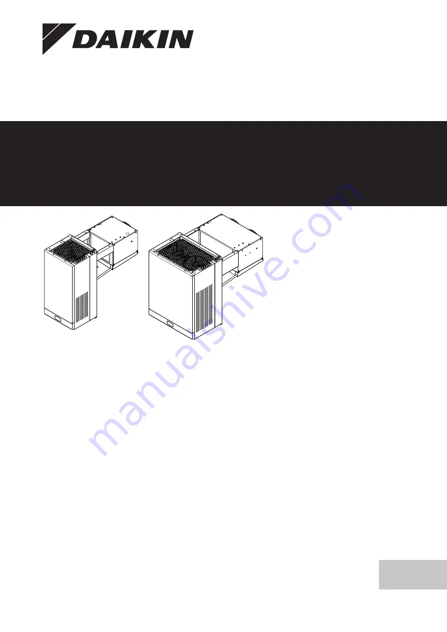
Page 7: ...Insulation accessory e Cold room roof f Condenser fan g High pressure switch h Electronic expansion valve with firewall i Evaporator j Evaporator fan k Thermistor l Defrost coil for drain pan m Drain...
Page 8: ...To install multiple units 415 4 5 Possible options for the unit INFORMATION Certain options may NOT be available in your country Three cable glands a b and c are provided to bring the option cables i...
Page 9: ...ronment e g sea breeze atmosphere This to prevent corrosion caused by high levels of salt in the air which can shorten the life of the unit If outside air is sucked into the cold room the temperature...
Page 10: ...e the blade is long enough to cut through the entire wall panel 5 3 Opening and closing the unit 5 3 1 To open the unit DANGER RISK OF ELECTROCUTION Do NOT leave the unit unattended when the service c...
Page 11: ...st be removed See below for more information To prepare the cold room for wall mounting 1 Make a cutout in the front wall of the cold room The cutout x y will accommodate the unit evaporator protrusio...
Page 12: ...old room 411 the optional insulation pad must be installed on the unit Refer to the installation instruction included in the insulation pad option 1 Install the insulation pad a at the back of the uni...
Page 13: ...pad c Cutout 4 With the unit in place fix it with 4 screws through the fixing holes a b In case of saddle mounting method 1 If not already done position the unit on a lifting table and secure it with...
Page 14: ...n the condenser part of the unit Most of the time this water evaporates in the overflow tank c that has hot refrigerant pipes d going through it This also works as a water cooling system for hot refri...
Page 15: ...must be connected to their main PCB controllers 1 Open the unit condenser front plate and electrical box cover See 5 3 Opening and closing the unit 410 2 Connect the BMS connector J4 of the secondary...
Page 16: ...suitable for 220 240 V and the total load of the control circuit must NOT exceed 4 A INFORMATION For the cold room lamp usually a LED bulb of 0 1 A is used with a maximum 0 3 A 4 Connect the wiring t...
Page 17: ...X4M 32C X4M 33C X4M 34C X4M 35C X4M 36C X4M 37C X4M 38C X4M 39C X4M 40C X4M K3M 33 34 4 9 F3 6 3A F4 6 3A 5 2 5 2 5 6 5 7 5 7 5 7 5 6 5 6 5 4 5 4 5 9 5 9 5 9 5 9 5 10 5 9 5 8 5 8 5 3 HMI ACU Q1 d c a...
Page 18: ...s 4 Select BLUETOOTH SCAN to view the controller devices available within a range of 10 m 5 Select the device to connect to Result BLE will blink on the user interface display to confirm that the conn...
Page 19: ...n Max UoM Menu a App 5 b Unit of measure 0 C 1 F 0 0 1 Pro 6 Display decimal point 0 Yes 1 No 0 0 1 Pro t1 Display on user terminal 0 not configured 1 value of S1 2 value of S2 3 value of S3 4 value o...
Page 20: ...m serial 0 no 1 yes 0 0 1 dFr b Defrost status 0 0 1 dFs b Defrost state idle dI b Maximum interval between consecutive defrosts 8 0 240 hours dP1 b Maximum defrost duration 45 1 240 min dP2 b Maximum...
Page 21: ...0 1 FOE Logical status of the digital light output 0 0 1 FOG Logical status of the digital output 0 0 1 FOI Logical status of the digital output 0 0 1 FOI_1 Logical status of the digital output 0 0 1...
Page 22: ...on for secondary unit 2 0 The controller regulates through the probe connected to itself 1 The controller regulates through the probe connected to the Primary unit 0 0 1 nrt_3 c Network temperature re...
Page 23: ...ontrol setpoint 4 0 25 10 C F StH Setpoint for humidity 90 0 0 CtL Sv Virtual probe read only 20 2 0 0 Sv_1 Virtual probe secondary unit 1 read only 0 0 0 Sv_2 Virtual probe secondary unit 2 read only...
Page 24: ...d Start timespan 5 day 0 00 00 0 00 00 23 59 59 tS5 time Start time datatype 5 0 00 00 0 00 00 23 59 59 tS6 d Start timespan 6 day 0 00 00 0 00 00 23 59 59 tS6 time Start time datatype 6 0 00 00 0 00...
Page 25: ...tatus is open if the switch is open As for the lights also the door status is shared to all controllers Every controller knows if the door s is are open or not and each controller can perform the acti...
Page 26: ...s will happen when a network connection fault occurs that lasts longer than the dI parameter setting Therefore the dI parameter must always be set 6 6 About the alarms To check and reset alarms error...
Page 27: ...t must be done by an authorised area technical assistance service that has proper training equipment and instructions for the dismantling They are also responsible for reuse recycling and recovery CAU...
Page 28: ...F3 Line aux fuse HMI User interface HMI cable User interface cable connection HPS1 High pressure switch 1 HPS2 High pressure switch 1 Symbol Meaning INV1 Inverter compressor 1 INV2 Inverter compresso...
Page 29: ...Thermistor evaporator inlet Th6 B Thermistor evaporator outlet Th7 B Thermistor condenser 10 3 Weight Model Type Weight LMSEY1A09AVM01 A 52 kg LMSEY1A13AVM01 LMSEY2A19AYE01 B 83 5 kg LMSEY2A25AYE01 WA...
Page 30: ...nal equipment Equipment made or approved by Daikin that can be combined with the product according to the instructions in the accompanying documentation Field supply Equipment NOT made by Daikin that...
Page 31: ......
Page 32: ...4P728170 1 2023 03 Copyright 2023 Daikin 4P728170 1 0000000N Verantwortung f r Energie und Umwelt...