


378-206
Rexnord
January 2019
3001 W. Canal St., Milwaukee, WI 53208-4200 USA
Supersedes 07-15
Telephone:
414-342-3131
Fax:
414-937-4359
www.rexnord.com
(PN-212395)
Owners Manual
•
Falk Quadrive Shaft-Mounted Drives Model A
(Page 6 of 53)
Sizes 5407-5608
4 .
JSC
— Fasten the trough end to the seal housing using
the hex head cap screws included in the drive shaft kit .
Refer to Table 3 for torque value . Proceed to Step 6 .
Table 3 — 5407JSC Trough End Fastener
Size & Tightening Torque
(Non-lubricated Fasteners)
Drive Shaft Diameter
3.000 & 3.437
Fastener Size
.750-10UNC
Tightening Torque, lb-ft (Nm)
245 (332)
5 .
JF
— (NOTE: If the driven shaft has not been machined
to Falk’s taper bore specifications per Manual 377-140
and a straight shaft is to be utilized, refer to Manual
377-144 for instructions) .
Install backstop prior to installation of drive (refer to
Appendix B) . Installation of internal backstops NOT
Factory-installed may require removal of mounting
flange, Ref . #12 . Remove cover from input end of hollow
shaft bore and save . Install the thrust plate and retaining
ring in the hollow shaft (refer to Figure 4) . Proceed to
Step 6 .
INSTALLATION
6 .
JR, JF & JSC
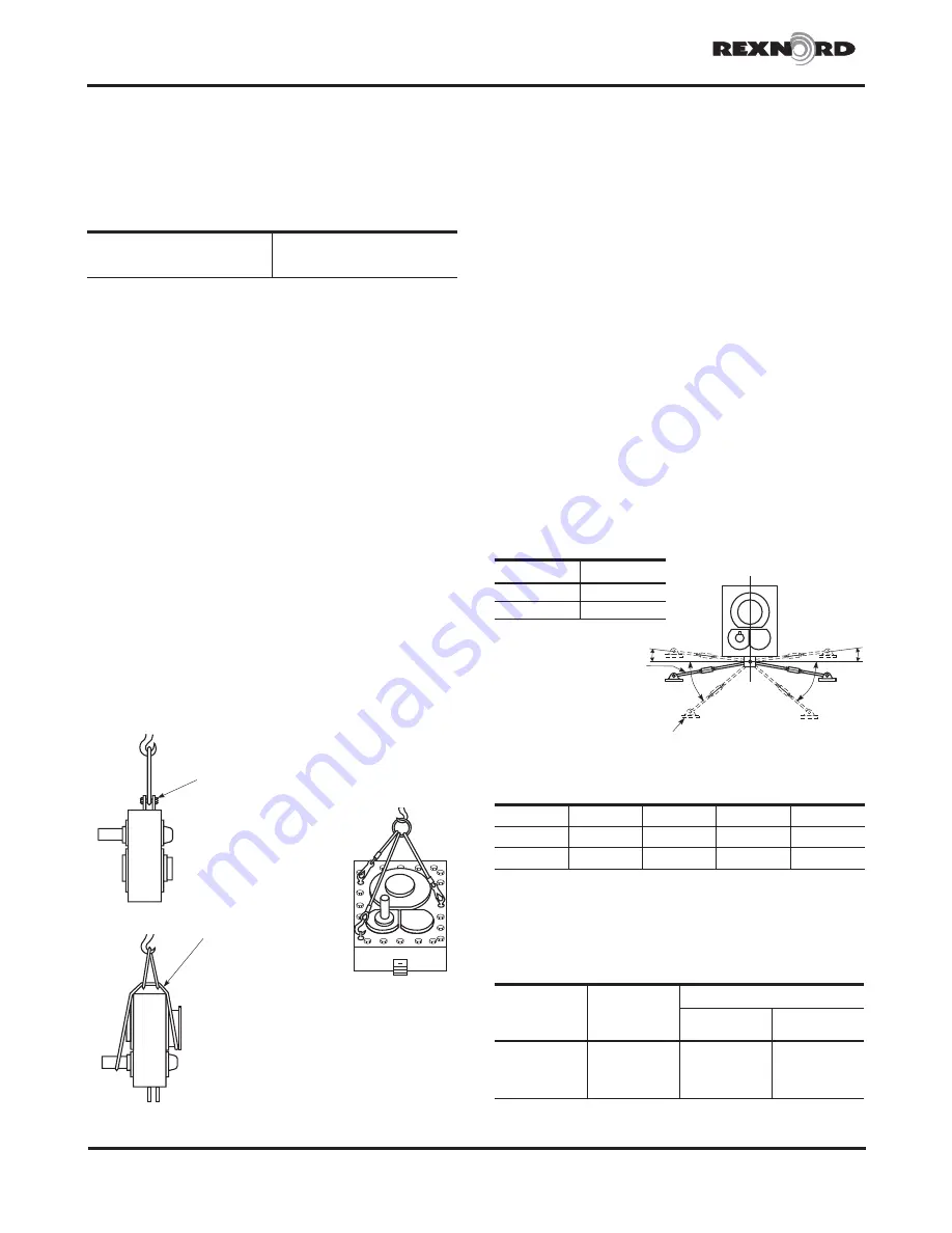
— Refer to Figure 7 for recommended
lifting method . In order to sling JR & JF drives as
illustrated, install the torque arm fastener in the torque
arm anchor brackets . Sling the drive from the fastener
as shown . For vertical installation, use (3) eyebolts as
illustrated . Eyebolt sizes are 1/2” for 5407 thru 5507
and 3/4” for 5608 . DO NOT remove sling until drive is
secured to shaft . Before lifting the drive into position,
rotate the high-speed shaft until the hollow shaft keyway
will be in position to line-up with the driven shaft key . JF
proceed to Step 11; JSC to Step 12 .
SLING FROM
LONG FASTENER
WITH NUT
SLING AROUNG
SEAL HOUSING
AND INPUT SHAFT
Figure 7
7 .
JR
— If the drive was received with a backstop
installed, the backstop must be temporarily removed
to facilitate mounting . Refer to Section II, Step 10 for
backstop removal instructions . Proceed to Step 8 .
8 .
JR
— Lift the drive into position and slide onto the drive
shaft taking care that the driven shaft key seats into the
hollow shaft keyway . DO NOT hammer or use excessive
force . Refer to Figure 8 for installation of the torque arm .
The exact position of the torque arm may vary within
the range shown . For torque arm mountings other than
shown, refer to Factory . If it is necessary to shorten the
torque arm assembly, cut the excess from either tie rod
end .
The support to which the clevis bracket is to be
fastened must sustain the torque reaction shown
in Table 4 . The maximum load reaction through the
torque arm occurs when the torque arm is located in
the extreme off angle position . Use Grade 5 fasteners
to anchor the clevis bracket; refer to Table 5 for the
fastener size and tightening torque .
Bolt the torque arm to both the clevis bracket and the
drive anchor bracket and tighten the bolts until seated
against the brackets . DO NOT bend the bracket as
clearance between the clevis brackets and tie rod is
necessary .
A
A
2°
2°
CLEVIS
BRACKET
TIE ROD
AND
TURNBUCKLE
Figure 8 — Torque Arm Mounting Positions
6 O’Clock Mounting Position Shown
Drive Size
A
5407-5507
30°
5608
25°
Table 5 — Tie Rod Clevis Bracket Fastener
Tightening Torque
Drive
Size
Fastener
Size
Tightening Torque — lb-ft (Nm)
Steel
Foundation
Concrete
Foundation
5407
1.000-8UNC
567 (768)
467 (633)
5415
1.250-7UNC
1050 (1424)
867 (1175)
5507
1.250-7UNC
1050 (1424)
867 (1175)
5608
1.250-7UNC
1050 (1424)
867 (1175)
Grade 5 fasteners required .
Table 4 — Load Reaction Through Tie Rod
Drive Size
5407
5415
5507
5608
Load
, lb
21840
26120
32940
40930
Load
, (N)
(97130)
(116170)
(146500)
(182060)
c
Load includes moment due to motor and motor mount with torque arm at
maximum angle .


