


378-206
Rexnord
January 2019
3001 W. Canal St., Milwaukee, WI 53208-4200 USA
Supersedes 07-15
Telephone:
414-342-3131
Fax:
414-937-4359
www.rexnord.com
(PN-212395)
Owners Manual
•
Falk Quadrive Shaft-Mounted Drives Model A
(Page 20 of 53)
Sizes 5407-5608
d . Refer to Table 17 and note the preload specified for
bearings Ref . #4A1 and 4A2 . Add to the upper and
lower limits shown, the axial movement obtained in
Step 6(c) . This will indicate the thickness of shims
to be removed to obtain the specified preload . For
example, if the preload in Table 17 is .005” to .007”
(0 .13 mm to 0 .18 mm) and the axial movement
was .007” (0 .18 mm), removal of shims with a total
thickness of .012” to .014” (0 .31 mm to 0 .36 mm)
will produce the desired preload . Table 15 provides
shim thicknesses for each shim pack to assist in
obtaining the desired results . Take into account the
compressibility of shim-gaskets from Table 16 .
e . Remove seal cage, Ref . #11, and remove shim-
gasket(s) as determined in Step 6(d) . Reattach the
seal cage and tighten fasteners to torque specified
in Table 14 .
Table 17 — Preload & Axial Settings –
Inch (mm)
Drive
Size
Bearings
Ref. #4A1 & 4A2
Shaft & Pinion
Ref. #2A3
Shaft & Pinion
Ref. #1A3 or 3A3
Bearing Preload
Axial Float
Axial Float
5407
.004-.006 (0.10-0.15)
.001-.003 (0.03-0.08)
.001-.003 (0.03-0.08)
5415
.005-.007 (0.13-0.18)
5507
.006-.008 (0.15-0.20)
5608
.008-.010 (0.20-0.25)
c
NOTE: For Sizes 5407 & 5415 equipped with a backstop, axial float
measurement must be within the following range: .001 preload to .001
float .
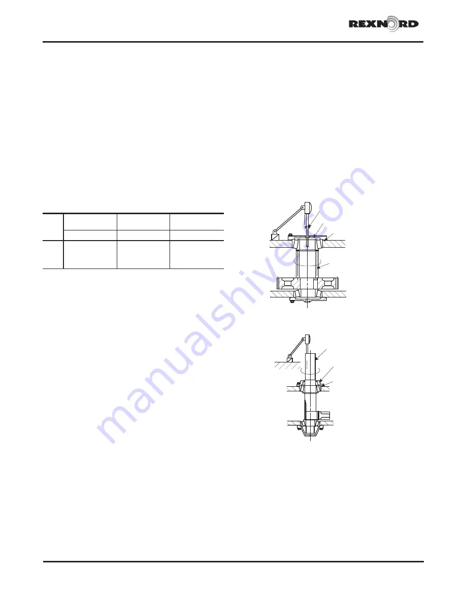
f . AXIAL FLOAT ADJUSTMENT, REF . #2A3 — Remove
pipe plug from center of shaft cover, Ref . #16, and
install a .375-16 x 2” or longer fastener thru the hole
in the shaft cover into the threaded hole in the pinion
shaft . Turn by hand until snug . Set up a dial indicator
with the probe on the fastener head as illustrated in
Figure 23 . Turn the fastener in a clockwise direction,
pushing and pulling the fastener to make certain
the bearings are properly seated . Measure the axial
float . Subtract from this reading the axial float for
Ref . #2A3 shaft found in Table 15 . This indicates the
thickness of shims to be removed . When removing
the shim(s) retain the .015” (0,38 mm) thickness
against the drive housing . Retighten fasteners and
recheck float . Readjust shimming, if necessary, until
proper axial float is achieved (Table 17) .
g .
AXIAL FLOAT ADJUSTMENT, REF. #1A3 or 3A3
—
Refer to Figure 24 and adjust float as follows:
Set up a dial indicator for determining axial
movement of the high speed shaft Ref . #1A3 or
3A3 . Lift upward with a twisting motion to obtain a
reading .
WARNING
: Cover keyway with tape to avoid
lacerations to the hand.
Subtract from this reading the axial float for shaft,
Ref . #1A3 or 3A3, found in Table 15 . This indicates
the thickness of shim(s), Ref . #31, to be removed .
When removing the shim(s), retain the .015”
(0 .38 mm) thick shim against the housing, Ref . #10 .
Retighten fasteners and recheck float . Readjust
shimming, if necessary, until proper float is achieved
(Table 17) .
7 .
SEAL INSTALLATION
Seals can be installed after all bearing adjustments
have been completed . Refer to Section II, Step 7, to
install seals, Ref . #22 & 23 . NOTE: When removing a
seal cage to install a seal, be sure to replace the same
shim-gaskets as removed to assure correct bearing
adjustments .
8 .
BACKSTOP INSTALLATION
If drive will be installed on the driven equipment
using the thrust plate and thrust plate fastener, install
the backstop at this time . Refer to Appendix B, for
installation instructions .
DRIVE IS READY TO INSTALL
— Refer to Section I .
TURN AND MOVE
BOLT TO CHECK
FLOAT
REF. #16 COVER
REF. #26 SHIM-GASKET
REF. #2A3
PINION
Figure 23
REF. #1A3/3A3
PINION & SHAFT
REF. #21 SEAL CAGE
REF. #31 SHIM-GASKET
Figure 24


