PART V TROUBLESHOOTING
5-2
ENGLISH
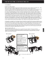
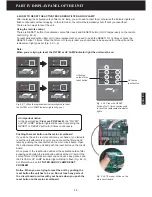
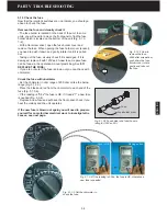
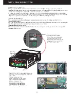
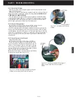
5.1.1 Check the electrical outlet and the front panel (Air Intake)
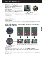
Sometimes, the unit does not operate because of the electrical outlet failure. Make
sure the power plug is inserted into the wall outlet correctly, or try to reinsert the
power plug (5.1.1-1). Check if other electrical appliances using the same electrical
outlet are working.
If the electrical outlet is correct, go head and check the front panel. There is an
actuator at the right bottom inside the front panel (Fig. 5.1.1-2). The actuator must
push down the two levers of the twin interlock switch to operate the unit. If the front
panel is detached or the actuator is deformed the unit does not work. Make sure the
front panel is installed properly and there are no dents or bends which would refrain
from closing the front panel correctly.
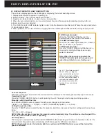
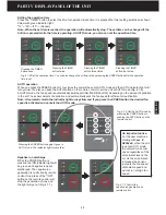
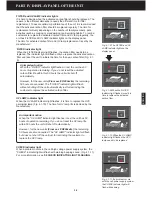
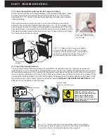
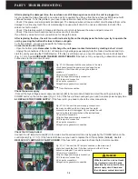
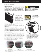
5.1.2 Check the interlock switches
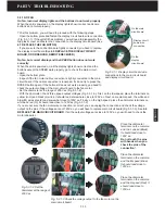
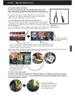
The unit comes with twin interlock switches to interrupt the unit operation when the front panel is opened by
accidence (Fig. 5.1.2-1). One switch is to interrupt the power cord Live line (White color) and the other is to interrupt
the Neutral wire (Black wire). It is important that the actuator must push down the two levers of the twin switches at
the same time to operate the unit. If one or two of them is not closed down or broken the unit will be no power. When
you check the interlock switches, open the bottom plate and visually check if the twin switches are damaged. If they
are cracked down by the actuator, replace the switches (See
6.1 REPLACE THE INTERLOCK SWITCHES
). If the
switches are OK, go ahead to check the fuse.
Fig. 5.1.1-1 Make sure the
power plug is tightly inserted
into the outlet .
Fig. 5.1.1-2 Make sure the front panel is installed
correctly so that the actuator is able to push down
the levers of the interlock switches. If the actuator is
deformed, some adjustment is needed in order for
the front panel to close the switches correctly.
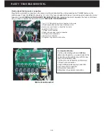
While the unit is on, do not
touch any electrical wires with
hands, especially the main
circuit board, power supply
circuit board and the unit power
contact terminals!
WARNING
Actuator
Interlock switch
actuator
Interlock switch
actuator on the front panel
Interlock switch
levers
Front panel
1
1
2
2
A
B
Fig. 5.1.2-1 The unit has two same interlock switches which are put together
by metal plate 1# (Adjustor plate) and secured to the bottom by metal plate 2#.
A shows the old model and B indicates the new model machines.
Summary of Contents for R200T
Page 69: ...ENGLISH NOTES ...


