PART V TROUBLESHOOTING
5-13
ENGLISH
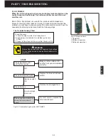
5.3.1 NO FAN
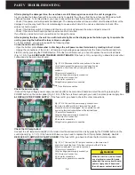
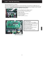
No fan, incorrect display lights and the buttons do not work properly
When the unit is powered on, the display lights show incorrect and some
buttons do not work properly.
To fix this problem, you will need to proceed with the following steps.
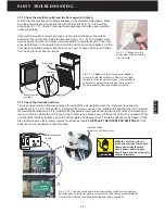
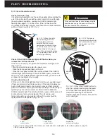
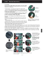
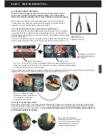
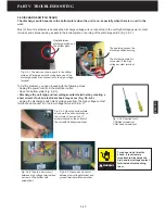
- Open the bottom plate and fasten the display circuit board wire connection
(Fig. 5.3.1-1). If the unit still has problem, you will need to disassembly the
top plastic cover and fasten the connection to the display circuit board (See
6.7 REPLACE THE FAN MOTOR
).
- If you are sure the connections are tightly connected, you have to replace
the display circuit board (See
6.9 REPLACE THE DISPLAY CIRCUIT
BOARD, ODOR SENSOR, REMOTE RECEIVER
).
No fan, but correct display and the SPEED button does not work
correctly
When the unit is powered on, all the display lights show correct and the
buttons except the SPEED work properly, go to check the main circuit
board.
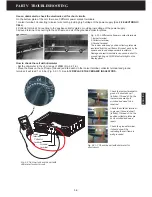
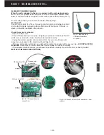
- Open the bottom plate.
- Inspect if the fan motor cable connection is tightly connected to the main
circuit board. If the cable connection is loosened, fix it and try to press the
SPEED button again. If the button still does not work properly, go ahead to
check the output voltage of the main circuit board to the fan motor.
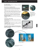
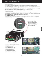
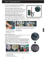
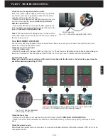
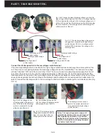
Fig. 5.3.1-3 Check the voltage output to the fan motor on the
main circuit board.
Fig. 5.3.1-1 Display circuit board wire
connections to the main circuit board
and display circuit board.
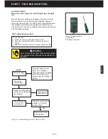
Fig. 5.3.1-2 Set the
ohmmeter at the range of
200V ac.
Place the ohmmeter
terminals on the common
and the L speed (Black).
It should read close to
120V ac.
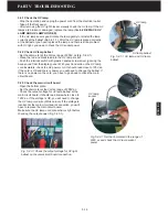
Do not touch the pins
with hands when you
check the pins of the
connection!
Place the ohmmeter
terminals on the common
and the M speed (Blue).
It should read close to
120V ac.
Place the ohmmeter
terminals on the common
and the H speed (Red). It
should read close to
120V ac.
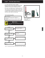
- Set the ohmmeter at the range of 200V ac (Fig.5.3.1-2).
- With the ohmmeter, check three speed output voltages (Fig. 5.3.1-3). First, on the low speed, place the terminals on
yellow (com) and black (L) wires, it should read somewhere close to 120V ac. Next, on medium speed, the white and
blue (M) wires should read somewhat close to 120V ac. Finally, on the high speed, place the ohmmeter terminals on
white and red (H), it should read close to 120V ac (Fig.5.3.1-2).
If you are not sure the fan motor wire connection is correct, you can unplug the connection and check the voltage
output on the pins. If the voltages are not 120V ac, you will have to replace main circuit board (Fig 5.3.1-3). See
6.6
REPLACE THE MAIN CIRCUIT BOARD
.
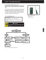
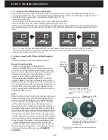
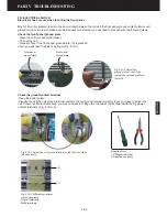
If all the output voltages are close to 120V ac, you will need to check the
motor capacitor.
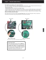
Display circuit
board wire
connection
On the main
circuit board
On the
display
circuit board
Summary of Contents for R200T
Page 69: ...ENGLISH NOTES ...


