PART III ELECTRICAL SYSTEM OF THE UNIT
3-6
ENGLISH
3.3 HIGH VOLTAGE POWER SUPPLY AND UNIT
POWER CONTACT BOARD
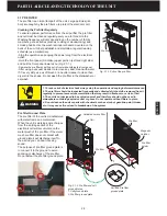
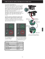
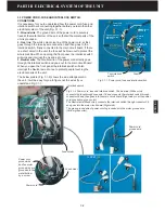
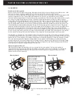
High voltage power supply
The power supply provides high and low voltages to the
cell through the power contact terminals. If the power
supply is broken the electronic cell cannot create
electrical field in the cell, failing to capture the particles
which are passing through the cell. It is necessary to
monitor the power supply working condition when the
unit is working. There are the red signal twin wires which
connect the power supply and the main circuit. When the
voltage on the signal wire is above 1.3V dc, the main
circuit board regards the power supply-cell system is
working correctly. Once the voltage on the signal wire is
less than 1.3V dc, the CHECK indicator light on the
display panel will flash with warning beeping sound.
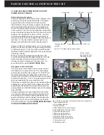
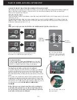
However, if the C10 resistance (Fig. 3.3-1) on the power
supply circuit board is broken the signal voltage will also
be decrease under 1.3V dc, the main circuit board also
lights the CHECK indicator light even if the power supply
is working correctly.
When you rotate the voltage output adjustor on the
circuit board with plastic flat head screwdriver, the high
and low voltage output will increase (clockwise) or
decrease (counter-clockwise) at the same time. For
some information, see
2.2 ELECTRONIC CELL
.
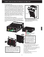
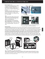
Unit power contact terminals
The unit power contact board has two power contact
terminals and one ground terminal. The high voltage
power supply provides high voltage (7.5-7.8KV DC) to
the ionizer wires and low voltage (3.5~4.5KV DC) to
positive collector plates of the cell through the two power
contact terminals (Fig. 3.3-2). The power supply and the
cell are grounded by the unit ground terminal.
If the power contact board (epoxy resin insulation board)
is damaged or wet, the high or low voltage wire of the
power supply will be short to ground, causing the cell
working failure and CHECK indicator light on the display
panel will flash.
The space between the high voltage terminal 1# (Fig.
3.3-2) and the board securing screws should be kept
enough space to avoid the sparking happening. Any
sparks will interfere with the display circuit board wire,
leading the incorrect work of the display circuit board.
For some information, see
5.8 SPARK BETWEEN HIGH
VOLTAGE TERMINAL AND SCREW
.
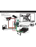
Fig. 3.3-2 The unit power contact board and wire connections.
1-High voltage terminal
2- Low voltage terminal
3-Ground terminal
4-High voltage wire of power supply
5-Low voltage wire of power supply
6-Power supply power cord
7-Power supply signal wire
8-Power supply ground wire
9-Discharge switch voltage wire
10-Discharge switch ground wire
11-Unit ground wire
12-Discharge switch
3
3
2
2
1
1
8
8
C10
Resistance
Fig. 3.3-1 The high voltage power supply.
HV wire
Ground wire
Voltage output
adjustor
Fuse (125V, 1A)
Power connection
Signal wire
connector
LV wire
4
4
5
5
7
7
6
6
9
9
10
12
10
11
12
11
Power contact
epoxy resin board
(insulation board)
Summary of Contents for R200T
Page 69: ...ENGLISH NOTES ...

