background image

PART VI  HOW TO REPLACE THE PARTS

6-17

ENGLISH

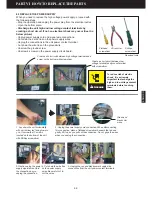
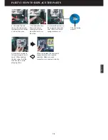
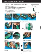
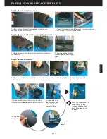
1.Remove 5 rivets on the epoxy 
resin power contact board with a 
hammer drill.

3. Fasten 5 rivets (3.2x7) on the power contact board with rivet gun.

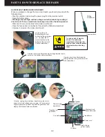
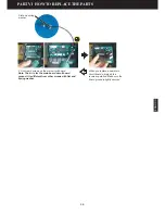
Install new ionizer wire by hooking eyelets over spring connectors with needle-nose pliers. Two 
eyelets hold an ionizer wire to cell.

2. Replace a new power contact board. Remember the ground 
terminal is placed between the board and cell bottom plate. 
1-High voltage terminal, 2- Low voltage terminal, 3- Ground terminal

Replace the power contact board

Replace an ionizer wire

1

1

2

3

2

3

Required tools

Needle-nose pliers

Summary of Contents for R200T

Page 1: ...ic shock do not perform any servicing other than that contained in the operating manual unless you are qualified to do so 2008 RespirAide Tech Inc R200 Ver 2 1 PART I GENERAL DESCRIPTION ON AIR CLEANING PART II AIR CLEANING TECHNOLOGY OF THE UNIT PART III ELECTRICAL SYSTEM OF THE UNIT PART IV UNIT DISPLAY PART V TROUBLESHOOTING PART VI HOW TO REPLACE THE PARTS R200T ENGLISH C Copyright CONTENTS C ...

Page 2: ...DOOR AIR QUALITY Particulates Gases Vapors and Odors Source Control Ventilation Air Cleaning AIR CLEANING TECHNOLOGY Mechanical Filtration Electronic Filtration Electret Media Filter Negative Ion Negative Ion Generator Ozone Ozone Generator OZONE LEVEL AND THEIR EFFECTS Activated Carbon Filter Ultraviolet Light Photo catalyst ...

Page 3: ...h care professionals are especially concerned about the long term effects of inhaling fine particles less than 2 5 microns because they can travel deep into the lungs where they can remain embedded for years or be absorbed into the bloodstream Asbestos and various substances in environmental tobacco smoke ETS are well known examples and some are recognized carcinogens Exposure to high levels of fi...

Page 4: ...s and drip pans clean is important for minimizing dust and particle accumulation and indoor mold growth within the system Source control also involves inspecting a building regularly inside and out for any signs of water damage which is a good indicator that moisture levels are high enough to support indoor mold growth The best way to prevent indoor mold growth is to eliminate all sources of exces...

Page 5: ...performance Electronic filtration Electrostatic Precipitators most commonly referred to as electronic air purifiers operate on electrostatic attraction to a collecting section usually called a electronic cell A typical two stage electronic cell has an ionizer section the front portion of the cell and a collector section the back portion of the cell The ionizer wires are maintained at several thous...

Page 6: ... that are magnetically attracted to allergens and other airborne contaminates which are positively charged The newly formed larger particles are than able to fall harmlessly to the ground and out of the air we breathe Fig 1 2 3 The electret media filter also called as hybrid filter or synthetic filter Oxygen molecules Ozone molecules Ozone ozone generator Ozone is a molecule with three atoms of ox...

Page 7: ...r day 6 days a week Continuous maximum ozone concentration allowable per U S Navy_ in confined quarters such as atomic submarines Maximum allowable limit for industrial public or occupied spaces in England Japan France the Netherlands and Germany 0 15 0 51 ppm Typical peak concentrations in American cities 0 200 ppm Prolonged exposure of humans under occupational and experimental conditions produc...

Page 8: ...254nm 100nm 100nm 400nm 200nm 300nm 280nm 315nm 400nm Ultraviolet UV Light UV light is not visible to the human eye It refers to the part of the wavelength spectrum below visible violet light and above x rays and gamma rays All light is a form of electromagnetic radiation The distinguishing aspect of UV light is the wavelength which is longer than x rays but shorter than visible light It is named ...

Page 9: ...es its participation in chemical reactions The most widely postulated reactions are shown as Fig 1 2 10 below Hydroxyl radicals and super oxide ions are highly reactive species that will oxidize volatile organic compounds VOCs adsorbed on the catalyst surface They will also kill and decompose adsorbed bio aerosols The process is referred to as heterogeneous photo catalysis or more specifically pho...

Page 10: ...onic Cell Work Exploded View of the Cell Part Numbers and Names of the Cell Cleaning the Electronic Cell Ozone Generation of the Cell Discoloration of the Cell ACTIVATED CARBON FILTER Replacing the Activated Carbon Filter UV LAMPS AND PHOTO CATALYST Replacing the UV Lamps NEGATIVE ION GENERATOR Control the Negative Ion Discharge by Remote Control 2 1 2 2 2 3 2 3 2 3 2 4 2 4 2 5 2 5 2 6 2 6 2 6 2 7...

Page 11: ...orne pathogen a Photo catalytic filter removes VOC s and a Negative ion generator Automatic Function The gas sensor odor sensor can let the unit automatically select the appropriate fan speed depending on the air quality detected Filter and UV Lamp Replacement Indicator The Filter life and UV Lamps replacement indicators tell you when to replace the Activated Carbon Filter and the UV lamp Safety M...

Page 12: ...an Motor Front Cover 15 Fan Motor Lower Plate 16 Fan Motor Side Plate 17 Fan Blade 18 Fan Motor 19 Fan Housing 20 Motor Capacity 21 Negative Ion Generator 22 Fan Motor Upper Plate 23 Negative Ion Generator Holder 24 Fan Motor Metal Mesh 25 Remote Control Receiver 26 Display Circuit Board 27 Display Circuit Board Wires 28 Odor Gas Sensor 29 Control Panel Cover 30 Plastic Top Cover 31 Unit Housing 3...

Page 13: ...etal mesh When the unit is working some charges from the ionizing section of the electronic cell will accumulate on the metal mesh of the pre filter If the metal mesh pre filter does not contact with ground plate it will discharge itself to the air and you can hear cracking sound The purpose of pre filter ground plate is to connect it to the ground to avoid sparking or discharge of the pre filter ...

Page 14: ... cell work The cell needs high voltage to the ionizing wires and low voltage to the positive plates of the collector section 1 High voltage power supply 2 High voltage output wire of the power supply Red color 3 Low voltage output wire of the power supply Black color 4 Unit power contact epoxy board and terminals 5 Power supply ground wire Green color 6 Ground screw 7 Main circuit board 8 Cell pow...

Page 15: ...eight 3 5kg Collecting surface area 3 75m2 Particle removal efficiency 90 95 0 3micron 0 5micron Power consumption 4 77W at high voltage of 7 8KV dc 200B 6 1 Cell handle x1 200B 6 2 Top plate unit x1 200B 6 3 Ionizer wire with eyelets x12 200B 6 4 Ionizer wire latch holder x2 200B 6 5 Ionizer wire latch x1 200B 6 6 Aluminum tube rod x10 200B 6 7 Collector positive plate x36 200B 6 8 Collector grou...

Page 16: ...urifier operating at peak efficiency it is important to wash the electronic cell regularly Washing frequency will vary depending on the air quality where the unit operates If the air is of very poor quality the efficiency of the cell will degrade rapidly and may necessitate weekly cleaning Under normal operating conditions the cell should be cleaned every one to three months When you hear frequent...

Page 17: ...om oxygen in the air This process is similar to photosynthesis in which chlorophyll captures sunlight to turn water and carbon dioxide into oxygen and glucose The formed activated oxygen is strong enough to oxidize and decompose organic materials or smelling gas and kill bacteria For more information see PART I GENERAL DESCRIPTION ON AIR CLEANING Replacing the UV lamp When the UV Lamps indicator l...

Page 18: ...egative ion discharge by remote control When the Neg Ion indicator light is on negative ions are discharged The negative ion generation is controlled by remote control One press of the Neg Ion on the remote control will stop the generation of ions and the indicator light will go out See Fig 2 5 2 3 below Fig 2 5 2 When the Neg Ion is on the negative ion generator is working Fig 2 5 3 Pressing the ...

Page 19: ...ARD Main circuit board Display circuit board HIGH VOLTAGE POWER SUPPLY AND UNIT POWER CONTACT BOARD High voltage power supply Unit power and ground contact terminals DISCHARGE SWITCH Discharge switch in the unit ODOR SENSOR Why the odor sensor does not work properly FAN MOTOR SPEAKER REMOTE CONTROL 3 1 3 1A 3 1B 3 3 3 3 3 3 3 4 3 5 3 6 3 6 3 8 3 9 3 9 3 10 3 12 3 13 3 7 3 2 3 4 3 6 ...

Page 20: ...rcuit board Remote receiver Speaker Odor sensor Display panel Negative ion generator Interlock switch and fuse Main circuit board B 120V 60Hz Interlock switch Interlock switch White White Green Yellow Green Yellow green Fuse Black White Pink white Electrostatic discharge switch Electronic cell Fan motor UV lamp and ballast Collector White White Negative ion generator Ionizer Black Black Red Red Re...

Page 21: ...tive ion generator Display circuit board Odor sensor Remote receiver Display panel UV lamp and ballast Interlock switch Interlock switch Transformer JZ4 JZ17 JZ11 JZ15 JZ16 JZ10 JZ18 JZ6 JZ8 JZ1 Blue Black White White Green Y Green Yellow Green Yellow green Fuse Black White Pink white Electrostatic discharge switch High voltage generator Ver 2 0 A B C D E F Electronic cell Black Red Fan motor UV l...

Page 22: ... cord wire 6 Voltage wire of discharge switch 7 Ground wire of discharge switch 8 Ground wire to the bottom 9 Ground wire of power cord 10 Motor ground wire The transformer is separated from the main circuit board and the power supply ground wire is grounded through the ground wire The motor ground wire is secured with power cord ground wire Fig 3 3 Units starting with ser R200xxxE 1 High voltage ...

Page 23: ...will also interrupt the Neutral wire at once to protect people touching the electrical parts of the unit The below picture Fig 3 1 2 shows the wire arrangement in the unit It will be easy for you to figure out the wires if you understand Fig 3 1 1 Fig 3 1 1 Power cord fuse and interlock switch Fig 3 1 2 Power cord fuse and interlock switch The Live line White color connects the fuse through connec...

Page 24: ...al wire The power cord is secured on the back of the unit by power cord strain relief bushing Power cord strain relief bushing Fig 3 1 3 Electrical power cord of the unit Fig 3 1 4 The fuse holder and power cord on the back of the unit 1 Fuse hoder 2 Power cord and strain relief bushing Ground Ground Live line White Neutural wire Black Live Neutural 1 1 2 2 Interlock switch There are two same inte...

Page 25: ...isplay circuit board wire Fig 3 2 1 Main circuit board display circuit board Relay Fan motor connection Reset button Melody chip Memory chip Microprocessor Power supply singnal wire connection Speaker connection Do not touch this area of circuit board with hand when the unit is on the voltage in this area is 120V ac If not electrical shock or personal injury will occur Main Circuit Board PWB1 The ...

Page 26: ...yers of material glued into a single entity These additional layers may serve a number of purposes including providing grounding to the board The threads on the surface of a circuit board are usually copper created either by laying down individual lines mechanically or by coating the entire board in copper and stripping away excess Since the 1980s most circuit boards use surface mounted components...

Page 27: ...it power contact board has two power contact terminals and one ground terminal The high voltage power supply provides high voltage 7 5 7 8KV DC to the ionizer wires and low voltage 3 5 4 5KV DC to positive collector plates of the cell through the two power contact terminals Fig 3 3 2 The power supply and the cell are grounded by the unit ground terminal If the power contact board epoxy resin insul...

Page 28: ...nd the ground to discharge the collector section of the cell Fig 3 4 1 Unfortunately the discharge switch has only one voltage contact plate it means the discharge switch cannot discharge the ionizer and collector section of the cell at the same time Because of the much more remaining charge on the collector plates generally it is recommended that the discharge switch should connect the low voltag...

Page 29: ...long the switch will not work even you already pulled out the cell from the front panel If the switch lever is too short when the front panel is closed there will be a spark between the voltage plate and ground plate inside the discharge switch The space between the voltage plate and ground plate should be kept more than 7 mm to avoid the sparks There are two ways to solve above problem 1 Install ...

Page 30: ...2 years Display circuit board Remote receiver Sensor window Remote receiver and circuit board Display circuit board wire Main circuit board datag wire Odor sensor Odor sensor and circuit board Sensor window An important notice For customer convenience the sensor working process was redesigned from the new machines From ser R200xxE so you do not need to adjust the odor sensitivity The sensor will a...

Page 31: ...If the electric motor is loaded too heavily the motor shaft will stop This is known as the stall speed and should be avoided The capacitor or condenser as it is sometimes called in an electric motor provides a time delay on the power arriving at the start windings of the motor to make the motor start The start or auxiliary windings are inserted in the motor at an angle to the run or main winding T...

Page 32: ...connected to the main circuit board and the ground wire is grounded firmly with power cord ground wire by a screw and nut H speed Red M speed Blue L speed Black Common Yellow Motor ground wire Green yellow Ground wire Capacitor wire Fig 3 6 2 The Motor capacitor is secured at the left fan housing metal plate by one screw Fig 3 6 3 The fan motor system Motor type Power requirement Rated Power Capac...

Page 33: ...7 1 If the unit is no melody you should check if the speaker wire connection is connected loosened or replace the speaker The speaker will be interfered by any sparks from cell or power contact terminals Speaker holder Speaker Melody chip IC4 Speaker wire Speaker wire connection Speaker wire connection Speaker wire connection I Melody chip IC6 Speaker wire connection Speaker wire The speaker 6V 0 ...

Page 34: ...32 Capacitor Circuit board LED LED Integrated Circuit Painted coat inside the keypads of the sticker Button contac circuit Remote control work process Pushing a button on a remote control sets in motion a series of events that causes the controlled device to carry out a command The process works like this You push the Speed button on your remote control causing it to touch the button contact benea...

Page 35: ...unit Switch the airflow rate Setting the operation time Auto operation Negative ion discharge Filter life and UV lamp indicator lights HOW TO RESET THE ACTIVATED CARBON FILTER AND UV LAMPS Using the remote control Pushing the reset button on the main circuit board 4 1 4 1 4 2 4 3 4 3 4 3 4 4 4 5 4 5 4 5 ...

Page 36: ...tells the time for UV lamp to be replaced CHECK Indicator Light Once the CHECK indicator light flashes red a check up for cell high voltage power supply system is required Note When the power is connected the CHECK indicator light will turn green and when the unit starts to run it will go out Connect the power When the power plug is inserted into the wall outlet all the indicators on the display p...

Page 37: ...PEED button again it will go to AUTO mode the AUTO indicator light will turn yellow The airflow rates Fan motor speeds change as shown below Low Medium High AUTO mode Low Fig 4 1 4 For more information see 3 6 FAN MOTOR R Fig 4 1 2 When the power plug is inserted into the wall outlet all the indicator lights on the display panel will light up for 2 seconds to check all indicator lights are OK Note...

Page 38: ...n you press the SPEED button for four times the unit will be set at AUTO mode and the AUTO indicator light will turn yellow You also can push the AUTO button on the remote control to set the unit at AUTO mode Fig 4 1 6 At AUTO mode the fan speed is automatically switched HIGH MEDIUM LOW depending on the amount of pollution in the air The sensor detects the pollution and automatically sets the fan ...

Page 39: ...ime for the new carbon filter Fig 4 1 9 Fig 4 1 11 If a problem occurs with the cell power supply system the CHECK indicator light will flash with beeping CHECK indicator light When a problem occurs in the cell high voltage power supply system the CHECK indicator light will flash with warning beeping sound Fig 4 1 11 For more information see 5 2 CHECK INDICATOR LIGHT FLASHING UV LAMP indicator lig...

Page 40: ... and the replacement light goes out Fig 4 2 1 2 Note When you are trying to reset the FILTER or UV LAMP indicator light the unit must be on Activated carbon filter reset button An important notice In the new machine From ser R200xxE the FILTER and UV LAMP indicator lights will be reset jut pushing the RESET1 or RESET2 button for 5 times continuously Pushing the reset button on the main circuit boa...

Page 41: ... LIGHT FLASHING NO FAN INCORRECT AIR FLOW NO UV LIGHT THE BUTTONS DO NOT WORK MELODY CHIMES FAILURE FILTER AND UV LAMP RESET PROBLEM SPARK BETWEEN HIGH VOLTAGE TERMINAL AND SCREW DISCHARGE SIWTCH SPARK ELECTRICAL SHOCK 5 1 5 6 5 12 5 15 5 17 5 18 5 19 5 22 5 23 5 25 ...

Page 42: ...hing them If not an electrical shock may occur 1 8 9 10 11 12 13 2 3 4 5 6 7 1 Flat head screwdriver 2 Phillips screwdriver 3 Nut screwdriver M3 4 Needle nose pliers 5 Wire cutter 6 Ohmmeter 7 High voltage probe 8 Nut wrench 9 Hot glue gun 10 Hammer drill 11 Rivet gun 12 Soldering iron 13 Wire ties REQUIRED TOOLS AND OPEN THE BOTTOM PLATE 3 Create a short circuit between low voltage terminal and g...

Page 43: ...ont panel OK Interlock switch OK Make sure the outlet is OK and the front panel is installed correctly Check the interlock switch Check the fuse Replace the damaged fuse Fuse is always blown out Check any short circuit or check the main circuit board Replace the broken interlock switch Fix short circuit or replace the main circuit board The Troubleshooting Chart To use this chart 1 Follow the step...

Page 44: ...ack wire It is important that the actuator must push down the two levers of the twin switches at the same time to operate the unit If one or two of them is not closed down or broken the unit will be no power When you check the interlock switches open the bottom plate and visually check if the twin switches are damaged If they are cracked down by the actuator replace the switches See 6 1 REPLACE TH...

Page 45: ... you are not sure if the fuse is blown out you can check with ohmmeter Check the fuse with ohmmeter Set the ohmmeter in ohm range of 200 ohm or like the below range Fig 5 1 3 3 Place the black and red from the ohmmeter to each end of the fuse Fig 5 1 3 4 If the reading is 0 0x the fuse is OK if it reads 1 a new fuse is needed Fig 5 3 4 Replace a new fuse and put back the front panel check if you h...

Page 46: ...there is a short circuit between the wires and parts around it Check if the main circuit board connection wires are short circuited If you find any wire short circuit you will need to change the wires After replacing the fuse the unit is on with indicator lights on the display panel but when you try to operate the unit by pressing the buttons the fuse is blown out again To fix this problem you can...

Page 47: ... on the control panel Press the SPEED button Fig 5 1 3 8 If the fuse is suddenly blown out you will need to replace the motor capacitor See 6 8 REPLACE THE FAN MOTOR CAPACITOR After replacing the motor capacitor the fuse is still blown out you have to replace the fan motor See 6 7 REPLACE THE FAN MOTOR 1 3 4 5 1 3 4 5 2 2 An Important Notice For the units starting with ser J200xxx Main circuit boa...

Page 48: ... START 3 Repeat all the steps until the air purifier checks out OK START Some of these steps expose dangerous high voltage Only qualified service technician should attempt this procedure WARNING 5 2 CHECK INDICATOR LIGHT FLASHING When the unit is turned on the Check Unit indicator light flashes and you hear warning beep sound Most of time this problem is due to damaged electronic cell high voltage...

Page 49: ...provide high and low voltages to the cell the voltage will be less than 1 3V dc on the signal wire If the signal wire itself is damaged the voltage will also be blow 1 3V dc 3 Discharge switch short circuit If the discharge switch is short circuited itself between the low voltage wire and the ground wire the voltage will be decreased under 1 3V dc Fig 5 2 3 The CHECK indicator light flashes when t...

Page 50: ...rt circuit As long as a short circuit occurs in the cell the voltage on the signal wire will be decreased less than 1 3V dc leading to the CHECK indicator light flashing Check if the CHECK indicator light still flashes when you remove the cell from the unit If the cell is not wet try to operate the unit after removing the cell Fig 5 2 1 3 Stop the operation and unplug the power cord Open the front...

Page 51: ...r supply See 2 2 ELECTRONIC CELL 2 Collector terminal Connecting to the positive collector plates providing low voltage of the power supply 3 Ground terminal Connecting to the cell frame and all of the grounded collector plates Check the ionizer terminal to ground it should show 1 infinite If it reads 0 0x the ionizer wires are short circuited and need to be repaired Check the collector terminal t...

Page 52: ...w voltage will be 3 5 4 5 KV when there is a cell in the unit If it reads less than 6 0 KV or no voltage you will have to further investigate other reasons Fig 5 2 2 4 After fastening the connections check the voltage output of the main circuit board to the power supply It should read close to 120V ac If not replace the high voltage power supply 1 Power supply connection 2 Power supply cord connec...

Page 53: ...heck the discharge switch If the CHECK light still flashes you also need to check the discharge switch Unplug the discharge switch low voltage wire connection from the unit low voltage contact terminal Fig 5 2 4 1 Try to start the unit If the CHECK light does not flash the discharge switch is damaged you will have to replace or repair it See 6 5 REPLACE THE DISCHARGE SWITCH Fig 5 2 4 1 Unplug the ...

Page 54: ...fan has incorrect speed rates Most of time this problem is due to damaged motor capacitor electric motor or motor wire connection loose or main circuit board failure However there are other reasons In order to make sure what causes this problem you will have to prepare yourself for some electrical work have the necessary tools ready and proceed with the following steps No fan Incorrect air flow ST...

Page 55: ...k the voltage output to the fan motor on the main circuit board Fig 5 3 1 1 Display circuit board wire connections to the main circuit board and display circuit board Fig 5 3 1 2 Set the ohmmeter at the range of 200V ac Place the ohmmeter terminals on the common and the L speed Black It should read close to 120V ac Do not touch the pins with hands when you check the pins of the connection Place th...

Page 56: ...no any sound 5 3 2 INCORRECT AIR FLOW The fan motor has three speeds air flow however the air flow is incorrect you will need to check the main circuit board fan motor and the power source Check the main circuit board Open the bottom plate Set the ohmmeter at the range of 200V ac Fig 5 3 2 1 Check the Low Medium and High speed output voltage on the main circuit board They should read close to 120V...

Page 57: ...m is because of a loose UV bulb which could be due to shipping and handling However there are other reasons In order to make sure what causes this problem you will have to prepare yourself for some electrical work have the necessary tools ready and proceed with the following steps Check UV lamp Visually check the UV bulb If it is broken or damaged replace it Make sure the UV lamp is in place corre...

Page 58: ...nel With your hand solid on the UV lamp cord insulators check the UV power cord It should read close to 120V ac If the cord is OK and there is power you will need to change the ballast If there is no power on the cord you have to go ahead to check the main circuit board 5 4 3 Check the main circuit board Open the bottom plate Set the ohmmeter at the Volt ac range of 200V ac Check the output voltag...

Page 59: ...ell is not placed correctly so there is a space between cell and unit epoxy resin power contact terminal This will cause a spark to interfere with the display circuit board wire causing a button freeze Fig 5 5 1 2 Adjust the power contact terminals so that the cell can contact the unit power contact terminals closely Fig 5 5 2 1 Some times especially when the air is moist a spark may occur around ...

Page 60: ...he speaker wire connection is tightly connected and make sure the IC6 or IC4 melody chip on the main circuit board is inserted correctly Unplug the problem speaker wire connection from the main circuit board and connect a new speaker to the main circuit board Fig 5 6 2 Fig 5 6 1 The speaker wire connections Fig 5 6 2 Check the main circuit board with a new speaker Melody chip IC4 Speaker wire conn...

Page 61: ... technician should attempt this procedure WARNING Fig 5 7 2 Troubleshooting chart for RESET PROBLEM Press the RESET buttons on the remote for 12 times continuously RESET buttons do not work Still not reset Still not reset RESET1 for activated carbon filter and RESET2 for UV lamps the unit must be plugged in when pressing the reset buttons Changing a new remote trying again Press the reset button o...

Page 62: ...There are two ways to reset the replacement lights Reset with remote control Connect the power plug into the wall outlet Press the POWER button on the remote control If the FILTER or UV LAMP indicator light flashes red it tells the remote control and the remote receiver of the unit are OK otherwise you will need to check the remote control or remote receiver on the display circuit board After repl...

Page 63: ...ote control or have no remote control on your hand you can reset the unit by pressing the reset button on the main circuit board Open the bottom plate Plug in the power cord you should hear the starting melody Push the reset button on the main circuit board One pressing will reset the FILTER replacement and pressing and holding for 6 seconds will reset UV LAMP If the unit is reset you can hear a b...

Page 64: ...o high from the power supply the spark may occur Fig 5 8 1 To fix this problem proceed with the following steps Unplug the power cord Open the bottom plate Paste a insulation tape or clear tape beneath the unit high voltage contact terminal or use hot glue gun to bond the screws Fig 5 8 2 Fig 5 8 1 Sparks between the high voltage contact terminal and the screw on the power contact board Fig 5 8 2 ...

Page 65: ...etween low voltage terminal and ground terminal with screwdriver Fig 5 9 4 Create a short circuit between high voltage terminal and a screw on the bottom with screwdriver WARNING To reduce risk of electric shock it is extremely important to discharge the high and low voltage contact terminals before touching them To fix this problem you can proceed with the following steps Unplug the power cord fr...

Page 66: ... dc in the new unit Fig 5 9 8 The new cell uses more powerful power supply than the old cell When there is no cell in the unit the voltage will increase to 10KV dc Fig 5 9 9 This test result shows if the discharge switch is connected to the high voltage contact terminal to discharge the ionizer section of the new cell may cause spark especially in moist air between the discharge switch voltage wir...

Page 67: ...Fig 5 10 2 Adjust the unit ground terminal so that it can contact the cell closely Check the ground contact terminal Open the bottom plate Visually check if the unit ground terminal contacts the cell ground terminal correctly If not you have to adjust the cell If there is still electrical shock you may consider to change the cell power contact board with the big power contact terminals Fig 5 10 2 ...

Page 68: ...board is grounded by its ground screw 4 4 The motor is grounded by ground screw 3 5 Finally all the electrical parts are grounded through metal casing to the ground screw 3 which is connected with power cord ground wire Electronic Cell Front Panel Cell Ground Contact Terminal Front Panel Ground Contact Plate Front Panel Ground Contact Plate Unit Ground Contact Terminal Fig 5 10 4 The eletrical gro...

Page 69: ...ENGLISH NOTES ...
Page 70: ...ACE THE POWER CONTACT BOARD REPLACE THE DISCHARGE SWITCH REPLACE THE MAIN CIRCUIT BOARD REPLACE THE FAN MOTOR REPLACE THE FAN MOTOR CAPACITOR REPLACE THE DISPLAY CIRCUIT BOARD ODOR SENSOR REMOTE RECEIVER REPLACE THE POWER CORD REPLACE THE FUSE REPLACE THE CERAMIC INSULATORS REPLACE THE SPEAKER 6 1 6 2 6 3 6 5 6 7 6 8 6 10 6 12 6 13 6 14 6 15 6 16 6 18 ...

Page 71: ...10 screws located on the bottom of the unit with Phillips screwdriver 2 Unscrew 2 screws on the interlock switch metal holder with the nut screwdriver and the Phillips screwdriver There are one flat washer and one spring washer beneath the nut 3 Cut down the wire ties on the interlock switch wires Be careful not to cut the wires 4 Gently unplug the black wire connection to the main circuit board 5...

Page 72: ...lder Ballast by a screwdriver Open the swing nut at the right side of the UV light blocker and remove the UV light blocker 1 Unplug the UV light cord from the left side of the UV lamp holder 2 Lift up the UV lamp holder with a screwdriver to remove it easily 3 Pull out the UV lamp holder from the 2 metal clips 1 Unplug the rubber column at each side of UV lamp holder Remove the sticker paper from ...

Page 73: ...ed facing toward you Unscrew the 10 screws located on the bottom of the unit with Phillips screwdriver 3 Gently unplug the power supply signal wires Hold the connection as you unplug the connection 4 Cut down the wire ties on the power supply wires Be careful not to cut the wires 5 Unplug the red and black power supply wire connections from the unit power contact terminals 2 Unplug the power suppl...

Page 74: ...Be careful not to cut the wires 9 Unscrew 4 screws on the power supply circuit board When opening the last screw hold the circuit board to avoid dropping down 8 Unscrew the screw on the unit ground terminal wire There are flat and spring washers on it Flat and spring washer When you replace the new power supply simply do the reverse operation Make sure each connection is connected correctly ...

Page 75: ...voltage wire connection of the power supply pushing down the terminal with screwdriver 2 Unplug the black low voltage wire connection of the power supply There are flat and spring washers beneath the nut 3 Unplug the black voltage wire connection of the discharge switch 4 Open 2 nuts at the left side of the board with Phillips and nut screwdriver Required tools Create a short circuit between low v...

Page 76: ...ips screwdriver You need to hold the circuit board protector plate as you open the screws 6 Open the nut on the ground terminal to remove ground wires with nut screwdriver When you change the epoxy resin power contact board simply do the reverse operation Make sure the board is secured outside the bottom ...

Page 77: ...ou Unscrew the 10 screws located on the bottom of the unit with Phillips screwdriver 2 Unplug the black voltage wire connection Do not hold the wire when you unplug the wire connection 3 Unplug the ground wire connection Hold the connection tightly when you disconnect the connection 4 Open the screw located on the discharge switch inside the unit In some units there are 2 screws on it 5 Push down ...

Page 78: ...onnections transformer fan motor power cord high voltage power supply UV lamp power supply signal wire speaker negative ion generator and display circuit board wire connections Transformer Speaker Power supply signal wire Power cord High voltage power supply UV lamp Fan motor Negative ion generator Required tools Create a short circuit between low voltage terminal and ground terminal with screwdri...

Page 79: ...uit board Note The 4th is for the main board circuit board ground it is different from other screws with flat and spring washer 1 2 3 4 4 4 Flat and spring washer When you replace a new main circuit board simply do the reverse operation Make sure the board ground is tightly secured ...

Page 80: ... connection 1 Take off the front panel and unscrew 4 screws with Phillips screwdriver Hold the upper cover when you unscrew the last screw to avoid dropping down After unscrewing 4 screws pull it down with two hands In some units there are 2 screws on the upper cover 2 Open the screws on the fan motor front cover After removing the fan motor front cover you can see the fan motor system 1 Push down...

Page 81: ...otor upper plate 1 Open a nut on the motor sheft with a nut screwdriver counter clock wise with the right side nut 2 Open 2 screws on the motor wires 3 Open another nut on the motor sheft with a socket wrench clock wise with the left side nut 4 Open screws on the fan motor side plate with Phillips and nut screwdriver 2 Open 10 screws on the plastic cover 6 screws for plastic top cover and 4 for co...

Page 82: ... fan motor front cover Follow step 1 procedure of REPLACE FAN MOTOR Unscrew the screw on the motor capacitor Unplug the capacitor wire connection with a needle nose pliers The capacitor is rating for 6uf 250V ac 1 Open the screw on the motor capacitor 2 Unplug the capacitor wire connection with a long nose pliers Required tools Needle nose pliers Phillips screwdriver ...

Page 83: ...ull out the display circuit board 1 Open 4 screws on the plastic control cover 3 Unplug the odor sensor wire connection from the display circuit board 1 Gently lift up the remote receiver circuit board with a screwdriver Gently unplug the display circuit board from the plastic control cover 2 Unplug the wire connection from the display circuit board 2 Remove 2 screws on the odor sensor and pull it...

Page 84: ...e power cord wires 1 Lay down the unit horizontally with unit bottom led facing toward you Unscrew the 10 screws located on the bottom of the unit with Phillips screwdriver 4 Open the screw on the ground wires 6 Grip the power cord holder with needle nose pliers and pull out the power cord at the same time 7 Pull out the power cord 5 Unscrew the screw on the power cord wires Note The power cord wi...

Page 85: ...h a new one For more information see page 5 3 1 Put the unit on the work table with a carpet mat so not to damage the outer casing 3 Take out the fuse with plastic cover and check the fuse The fuse is rating for 125V 2A 2 Open the fuse holder cover with a flathead screwdriver Gently press down and rotate it until it spring out Note Some units have the fuse holder at the bottom front of the unit yo...

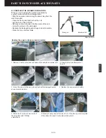
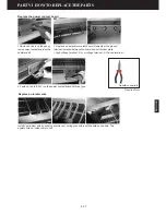
Page 86: ...place the damaged square shape ceramic insulator Close the top or bottom plate 1 Remove 4 rivets on the front and back of the cell with a hammer drill 2 Open the top or bottom plate of the cell 3 Loose the screw on the one side and pull out the damaged square shape ceramic insulator 4 Replace the new ceramic insulator 5 Fasten the 2 screws on each side of the side plate with 2 Phillips screwdriver...

Page 87: ... ionizer wire by hooking eyelets over spring connectors with needle nose pliers Two eyelets hold an ionizer wire to cell 2 Replace a new power contact board Remember the ground terminal is placed between the board and cell bottom plate 1 High voltage terminal 2 Low voltage terminal 3 Ground terminal Replace the power contact board Replace an ionizer wire 1 1 2 3 2 3 Required tools Needle nose plie...

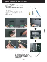
Page 88: ...der the wires to the speaker Install the unit handle 1 Gently lift up the corner of the handle with the flat head screwdriver 2 Pull out the handle 3 Take out the speaker from the handle hole 4 Remove the wires from the speaker with soldering iron 5 Attach the wires to the new speaker with soldering iron Flat head screwdriver Nut screwdriver Required tools Soldering iron For new units the speaker ...

Page 89: ...RespirAide Tech Inc 13 100 Hanlan Road Woodbridge Ontario Canada L4L 4V8 Tel 1 866 874 2532 Fax 1 905 850 5553 www respiraide com ...

Reviews: