REGULA 7517A User Manual Download Page 18

18

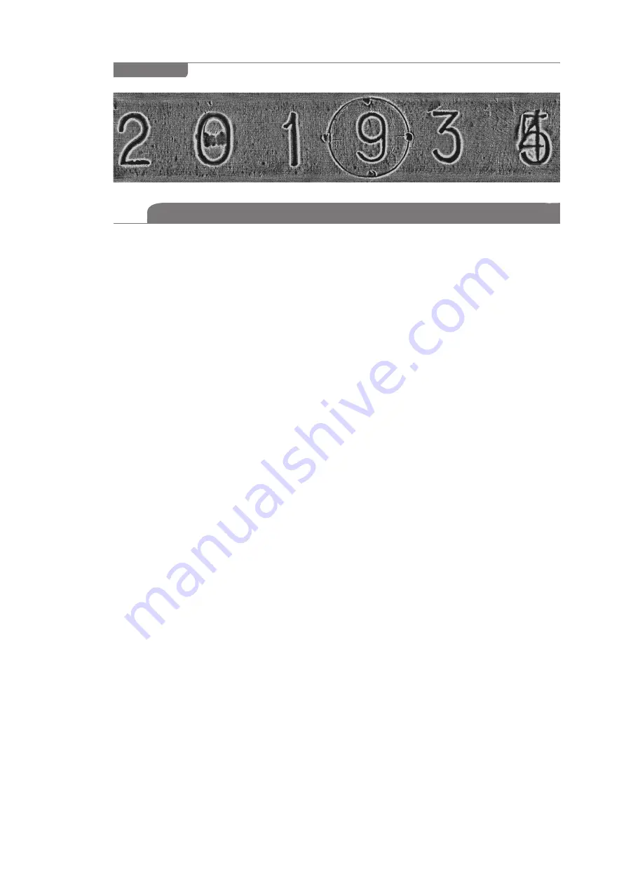
Magneto-optical visualization of the test object surface through the layer with thickness of 0,1 mm. 


Spatial resolution is around 80 μm.

Figure 4

2.2.1.3 MOV USB device intended use

The MOV USB device performs the following operations:


z

magnetic copy stitching,


z

extracting a used magnetic copy,


z

processing and analyzing magnetic copy stitching,


z

documenting examination results.

Magnetic copy stitching:


z

Ensure that no magnetic tape is present in the OMB tape drive tract — neither the red 

LED “MT in the buffer” (Figure 3, pos. 3), nor the green LED “MT in the tract” (Figure 3, 

pos. 3) is on. Otherwise, first remove the previous magnetic copy.


z

For plastic MT. Put the MT with its working surface 

(of  brown  colour)  facing 

down (facing the MOV USB device). It should be noted that when using ½’’ MT, it is 

inserted into a paper cartridge beforehand. Then put the ½’’ MT with its working surface 

(of brown colour) facing down while the paper cartridge is located on top of MT.


z

Straighten MT holding it by its edges and insert it into the tape drive (Figure 3, pos. 1). 

Move MT into the tape drive to a depth of 30 mm (until blocked). The red LED (Figure 3, 

pos. 3) lights up confirming the state “MT in the buffer” and the electric motor starts to 

capture the tape. Move the tape further inside the tape drive tract until it is captured by 

the drive shaft of the OMB. The green LED (Figure 3, pos. 3) lights up confirming the state 

“MT in the tract”).

 Release the MT strip and it will move forward automatically. 


z

Wait for approximately 5 seconds to load the potentially informative sector of the magnetic 

copy  into  MOV  zone.  Start  the  stitching  process  by  corresponding  software  command. 

The  stitching  process  is  confirmed  by  the  green  LED  blinking  (Figure  3,  pos.  3)  with 

the meaning “MT in the tract”. The first visualization sub-frame appears on the PC screen.


z

Control the quality of stitching visually. When signs of low quality of magnetic copying 

are observed (due to MT non-contact with the examined surface, MT or scanner warp 

during copying, etc.), it is possible to stop the stitching process by clicking “Eject MT”. 

As  soon  as  MT  is  returned  to  the  buffer,  extract  it,  demagnetize,  and  make  another 

magnetic copy in conformity with paragraph 2.2.2.3.


z

If  magnetic  copy  quality  is  satisfactory,  stitching  can  be  continued  until  the  end  of 

the informative MT area and then stopped by clicking “Eject MT”, or you can wait until 

OMB 

stops in automatic mode (“MT end” LED comes on).

Extraction of the used magnetic copy


z

As soon as the command “Eject MT” is executed by the 

OMB

, used MT automatically 

returns to  the  buffer —  to  the  tape  drive  or  to  the  bunker  (to  the  closest  location). 

The green LED “MT in the tract” fades and the red LED “MT in the buffer” comes on 

indicating that MT stopped moving. 

Do not remove an MT strip from the tape drive 

until it stops completely and the LED “MT in the tract” is off!


z

Take MT by its edges and remove it from the buffer. The red LED “MT in the buffer” is to 

go out. Then the used magnetic copy is to be demagnetized for reuse and placed into 

the 

CMS

 case or it should be stored for further use.

Summary of Contents for 7517A

Page 1: ...WARE AND SOFTWARE SYSTEM FOR FORENSIC EXAMINATION OF FIREARMS AND AMMUNITION SERIAL NUMBERS REGULA 7517 MAGNETO OPTICAL DEVICE REGULA 7517A USER S GUIDE Certified Quality Management System Regula Ltd...

Page 2: ......

Page 3: ...sories Set MCAS 13 1 2 3 Personal Computer PC 14 1 2 4 Software 15 1 2 5 Spare Parts and Repair Kit SPRK 15 2 INTENDED USE 16 2 1 Device Intended Use 16 2 1 1 Safety measures and operating limitations...

Page 4: ...ssories set MOI magneto optical image MOV magneto optical visualization MOV USB device USB device for magneto optical visualization OMB optic mechanical block MT magnetic tape SPRK spare parts and rep...

Page 5: ...ining and get clearance to perform expert examination in the field of trace evidence z z be an OS Windows user z z study techniques of authenticity verification of firearms and ammunition serial numbe...

Page 6: ...laboratory conditions due to the fact that the device provides high quality results visual evidence and uses non destructive magneto optical methods In case any changes in serial numbers are detected...

Page 7: ...than 5 years Operation warranty period 12 months from the date the device is delivered to the customer Storage warranty period 12 months Dimensions In transportation packaging not more than 350 280 22...

Page 8: ...sories 1 box 1b Peripheral examination tools Regula 7516 body case Regula 7516 Software PC drivers and utilities CD folder CD 1 OS Windows XP CD 2 MS Office CD 3 Special software for managing USB devi...

Page 9: ...where it is automatically detected and introduced into the tape drive tract Then it is scanned step by step by a sensor designed on the basis of a magneto optical crystal Magneto optical visualizatio...

Page 10: ...g with fusible metals dot welding and pressing in fragments See paragraph 2 2 1 2 for the details of the device operational check up using the test object Test object specifications The test object se...

Page 11: ...r s name and or trade mark z z manufacturer s model identification z z device serial number in compliance with the numbering system of the manufacturer z z date of manufacturing year and month z z rat...

Page 12: ...te time of input of a magnetic copy of the number platform 15 sec OS WindowsXPorlater Format of image files BMP PCX GIF JPG PC monitor size 12 Approximate size of an image file of the number platform...

Page 13: ...he copy reflects relief and structural inhomogeneity of the material Permanent magnets of the combination magnetic scanner CMS concentrators serve as sources of magnetic stray fields excitation z z De...

Page 14: ...ced examination of metal structure of objects is the eddy current scanner supplied optionally Its specifications are given in the user s guide to eddy current magnetographing device Regula 7517B Magne...

Page 15: ...ion results Detailed description of NUCA EYER software is given in the corresponding user s guide Spare Parts and Repair Kit SPRK Function SPRK is intended for routine maintenance and repairs of the d...

Page 16: ...z Consider operating limitations for the components of the device in conformity with paragraph 2 2 2 2 1 2 1 1 Failure to observe operating limitations given in paragraphs 2 1 1 and restrictions on th...

Page 17: ...rnal power supply source The device can be powered by the internal autonomous PC battery In this case power supply cables are not connected z z Switch on the PC Start the OS and launch NUCA EYER softw...

Page 18: ...d it will move forward automatically z z Wait for approximately 5 seconds to load the potentially informative sector of the magnetic copy into MOV zone Start the stitching process by corresponding sof...

Page 19: ...mined number Measure geometric dimensions of the images of the digits and analyze their position The software allows measuring linear and angular image dimensions z z Analyze examination results Docum...

Page 20: ...Figure 5a to move the MT strip Figure 5 pos 3 through the slot beyond the edge of the blade Figure 5 pos 2 z z Take the MT by its edge Figure 5 pos 3 and pull it out for a required length relative to...

Page 21: ...netized MT Inserting MT strips into the cartridge and extracting them Figure 6 d c b 1 cartridge for storing MT 2 magnetic clamp 3 MT 1 2 To insert MT strips into the cartridge do the following Roll u...

Page 22: ...irty MT surface greasy film water solvents chemical solutions particles of dust rust metal etc MT surface should be cleaned with alcohol using a special container from the SPRK Figure 7d MT with consi...

Page 23: ...tic MT in the conditions which improve the quality of magnetic copying e g for examining the relief and structure of aluminum objects for examining weak internal stresses in ferromagnetic objects for...

Page 24: ...h a magnetic clamp Figure 9 pos 2 z z Put the MT strip upon the prepared number platform and fix the MT end on the examined surface using a magnetic clamp avoid warps and shifts relative to the examin...

Page 25: ...spring clip z z Select the CMS concentrator according to the properties of the examined object z z Make a magnetic copy Lower the concentrator of the magnetic scanner unto the fixed MT strip and slig...

Page 26: ...ed object may appear z z Put the magnetic copy into the corresponding cartridge for storing MT see Figures 6a b The one for storing MT with recorded data is marked with red marker If necessary use the...

Page 27: ...ing the cleaning tape wait for at least 3 minutes until the tape drive surfaces get dry before starting device operation Rate of one time ethyl alcohol application 0 5 g Maintenance of the MOV USB dev...

Page 28: ...surface measure the thickness of lacquer and paint coating When examining the stitched image there are image fragments irrelevant to the examined object MT is not completely demagnetized Demagnetize t...

Page 29: ...the button of the pressing roller block It is strictly prohibited to use metal instruments for extracting foreign objects from the tract If the described methods are ineffective it is recommended to a...

Page 30: ...screw for about 1 mm Then put pieces of cardboard on the arrises and tighten plastic straps Figure 12 pos 2 The device is to be stored in climatic conditions given in paragraph 5 Protect the device fr...

Page 31: ...ULA Ltd Address for mailing claims with regard to the quality of the device 1 Volokha Street Office 314 Minsk 220036 Republic of Belarus Phone 375 17 2862825 Fax 375 17 2136897 e mail support regulafo...

Page 32: ...1 Volokha Street Office 314 Minsk 220036 Republic of Belarus Phone 375 17 2862825 Fax 375 17 2136897 e mail mail regula by http www regulaforensics com...

Reviews: