74
ST4000 Plus Wheel & Tiller Autopilots Owner’s Handbook
When the autopilot is not in use, the complete rod assembly may
be unscrewed to leave the cockpit unobstructed.
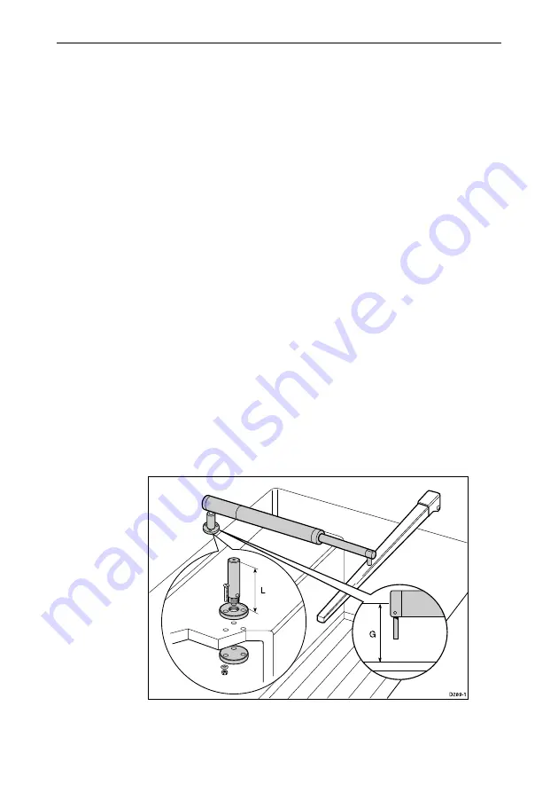
Pedestal socket mounting
It may be necessary to raise the height of the drive unit mounting
socket. A pedestal socket assembly must be used.
1. Lock the tiller on the yacht centre line.
2. Establish the standard control dimensions
A
and
B
.
3. Measure dimension
G
ensuring the autohelm actuator is
horizontal.
4. Select the pedestal socket assembly from the table shown.
Installation
1. Mark the position of the mounting flange on the cockpit seat/
counter.
2. Ensure that control dimensions
A
and
B
are correct.
3. Mark and drill three 6†mm (1/4†in) diameter clearance holes
(ignore the two inner holes).
4. Mount the flange using three 6†mm (1/4†in) diameter bolts, nuts
and washers (make sure that the back plate is installed correctly
and bed the flange on a thin coat of silicone rubber sealant).
5. Screw the mounting socket firmly into place.
When the autopilot is not in use, the mounting socket may be
unscrewed to leave the cockpit unobstructed.
Summary of Contents for ST4000 Plus
Page 2: ...ST4000Plus Wheel Tiller Autopilots Owner s Handbook Document number 81131_4 Date 18thApril1999...
Page 3: ...2 Titleof handbook...
Page 27: ...14 S T4000P lusWheel TillerAutopilotsOwner sHandbook...
Page 49: ...36 S T4000P lusWheel TillerAutopilotsOwner sHandbook 1 1 OR Adjusting User Setup Values...
Page 84: ...C hapter6 Installation 71...
Page 93: ...80 S T4000P lusWheel TillerAutopilotsOwner sHandbook...
Page 109: ...96 S T4000P lusWheel TillerAutopilotsOwner sHandbook...
Page 117: ......


