60
ST4000 Plus Wheel & Tiller Autopilots Owner’s Handbook
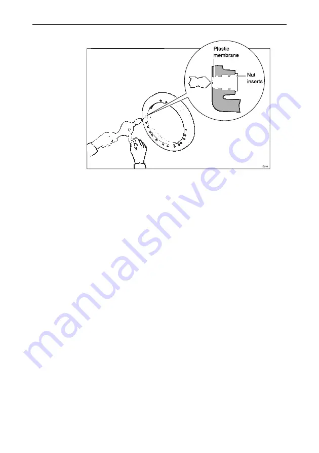
1. For 4 spoke wheels, use a 4.0†mm (5/32†in) drill to open out the C
pilot holes to gain access to the additional mounting points.
2. The plastic membrane covering the additional nut inserts is only
1.0†mm (0.04†in) thick. Care must be taken to ensure that the nut
inserts are not damaged when drilling.
3. Mount the drive between the wheel and the pedestal ñ three sets of
clamps are supplied to accommodate different spoke diameters.
Marked alongside each clamp is a range of spoke diameters. The
appropriate clamps are broken off as required.
4. When the actuator is fitted to a dished wheel, use the supplied
spacers to prevent distortion of the drive unit when the fixing bolts
are tightened.
Fitting to metal wheels
Remove the wheel and attach the drive as follows:
1. Place the drive unit with the clamping face uppermost ie. drive
motor and gearbox tube downwards.
2. If the wheel is dished, position one spacer at each of the three
attachment positions.
3. Place the wheel on top of the drive unit making sure the face which
is nearest the pedestal is downwards.
4. Fit the clamps over the spokes and lightly tighten the bolts
supplied.
Summary of Contents for ST4000 Plus
Page 2: ...ST4000Plus Wheel Tiller Autopilots Owner s Handbook Document number 81131_4 Date 18thApril1999...
Page 3: ...2 Titleof handbook...
Page 27: ...14 S T4000P lusWheel TillerAutopilotsOwner sHandbook...
Page 49: ...36 S T4000P lusWheel TillerAutopilotsOwner sHandbook 1 1 OR Adjusting User Setup Values...
Page 84: ...C hapter6 Installation 71...
Page 93: ...80 S T4000P lusWheel TillerAutopilotsOwner sHandbook...
Page 109: ...96 S T4000P lusWheel TillerAutopilotsOwner sHandbook...
Page 117: ......


