RG25DH Operation • Service • Maintenance • Parts Manual
800.392.2686
37
Maintenance
2. Reinsert into the threaded holes in the hub.
3. Turn each bolt by small equal amounts until the tapered
hub disengages.
Hydrostatic drive
The drive itself contains no adjustment. The ground travel
control lever however, when in automatic neutral position,
should not allow any forward or reverse creeping of the
machine.
Adjusting Linkage to Neutral
The mounting bracket has three positions when mounting
to frame. It will rarely, if ever, be necessary to change the
position as received from the factory. The ground travel control
cable passes through a hole in the mounting bracket and
has a lock nut on each side of the bracket leg to securely
position the cable. Adjustment at this point probably won’t
be necessary unless the cable itself is being replaced. The
hydrostatic direction lever cable has a ball connector at it’s
tip, which anchors the control cable through the spring loaded
ball joint connector, pushing the connector allows it to be
detached from the ball easily without tools.
1. Jack up the machine so the wheels clear the ground by
1 to 2 inches. Make sure unit is secured safely so that
it wont tip accidentally. (While it is not necessary to
remove the left hand wheel it is strongly recommended
to do so to avoid possible injury.)
2. Start the engine and let idle.
3. Disconnect the ground travel control cable from the ball
joint and loosen the lock nut on it’s threaded shaft.
4. The directional lever has a total movement of approx..
3” at the ball, with the midpoint being “neutral”.
5. With the engine idling, move full forward and full reverse
and then slowly bring the lever to it’s center neutral
position or until all movement of wheel and hub stops.
6. Adjust the ball joint connector on the cable by screwing it
in or out on the threaded shaft, until it can be reconnected
to the ball without activating the hydrostat.
7. Once adjusted correctly, tighten the lock nut on the
cable shaft, remount wheel, remove blocks and jack.
Test machine.
Hydrostatic Disengagement
When the engine is not running the machine can not be
moved since the hydrostatic drive is in the locked position.
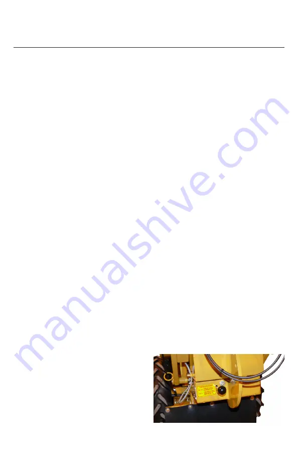
The Hydrostat also has a “By-Pass” control (1) which enables
the operator to manually move the machine when desired.
This control is located at the rear of the machine - lower left
hand side and is clearly identified.
To put the machine in “free wheeling” mode, lift the the
“by-pass” lever and push it all the way in, locking it in place
by allowing the last slot in lever to engage the frame. To
return it to powered travel, lift the “by-pass” lever, pull it out
to the second slot in lever and engage it into the frame in
that second slot.
Brake
The service brake is a disc type assembly with rotor attached
to a shaft on the hydrostat/differential transfer case, located on
the the underside of the frame. The brake pads are actuated
when tension is applied to the brake cable by pulling on the
brake handle.
Clutch
• When starting up a NEW clutch, it must be burnished-in
with engine running at half-speed (1600-1800 rpm, mid
way between slow and full throttle).
• Burnish-in the NEW clutch by cycling it 20-30 times:
switching the clutch ON for 10 seconds and then
switching OFF for 50 seconds to allow for proper cooling
between each cycle.
This prevents the risk of galling, caused by prematurely
imposing a full load on the new clutch.
Bendix Starter Drive - Service
Follow the directions found in the Engine Manual.
Solenoid Shift Starter - Have
Cleaned
Follow the directions found in the Engine Manual.
Cooling Shrouds - Remove and
Clean Area
Follow the directions found in the Kohler Engine Operation
Manual.
Oil Cooler Fins - Check and Clean
Area
Follow the directions found in the Kohler Engine Operation
Manual.
Spark Plug - Check Condition and
Gap
Follow the directions found in the Kohler Engine Operation
Manual.
Summary of Contents for RG25HD
Page 48: ...RG25DH Operation Service Maintenance Parts Manual 48 Troubleshooting ...
Page 49: ...RG25DH Operation Service Maintenance Parts Manual 800 392 2686 49 Troubleshooting ...
Page 50: ...RG25DH Operation Service Maintenance Parts Manual 50 Troubleshooting ...
Page 51: ...RG25DH Operation Service Maintenance Parts Manual 800 392 2686 51 Troubleshooting ...
Page 52: ...RG25DH Operation Service Maintenance Parts Manual 52 Troubleshooting ...
Page 53: ...RG25DH Operation Service Maintenance Parts Manual 800 392 2686 53 Troubleshooting ...
Page 54: ...RG25DH Operation Service Maintenance Parts Manual 54 Troubleshooting ...
Page 55: ...RG25DH Operation Service Maintenance Parts Manual 800 392 2686 55 Troubleshooting ...
Page 56: ...RG25DH Operation Service Maintenance Parts Manual 56 Troubleshooting ...
Page 57: ...RG25DH Operation Service Maintenance Parts Manual 800 392 2686 57 Troubleshooting ...
Page 66: ...RG25DH Operation Service Maintenance Parts Manual 66 Hydraulic Drive Assembly ...


