4.8.4
4.8.5
4.8.6
Draining tap
These must be located in accessible posi-
tions to permit the draining of the whole sys-
tem. The taps must be at least 15 mm nomi-
nal size and manufactured in accordance
with BS 2870 1980.
Air release points
These must be fitted at all high points where
air will naturally collect, and must be sited to
facilitate complete fitting of the system.
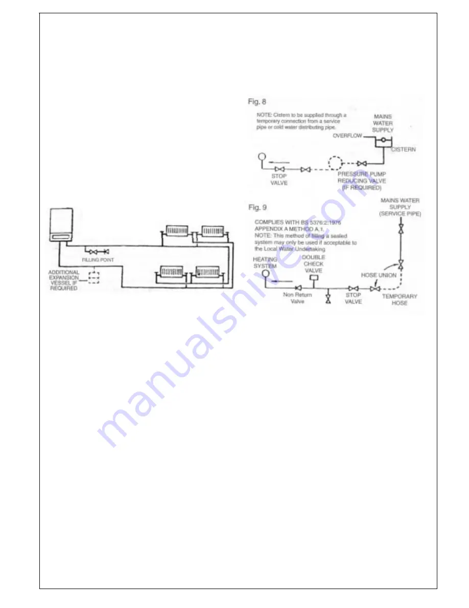
The appliance has an integral sealed expan-
sion vessel to accomodate the increase of
water volume when the system is heated. It
can accept up to 1.5 gal (7 Its) of expansion
water. lf the appliance is connected to a sys-
tem with an unusually high water content,
calculate the total expansion and add addi-
tional sealed expansion capacity as appro-
priate (Fig. 7).
In general modern systems will present no
problem.
Fig. 7
4.8.7
4.8.8
Mains water feed: central heating
There must be no direct connection to the
mains water supply, even through a non-
return valve, without the approval of the
Local Water Authority.
Permissible methods of filling
Cistern method (Fig. 8).
The system may be filled by one of the fol-
lowing methods. Through a cistern used for
no other purpose, via a ballvalve perma-
nently connected directly to a service pipe
and/or cold water distributing pipe. The stat-
ic head available from the cistern should be
adequate to provide the initial system
design pressure.
The cold feed pipe from the cistern should
include a non-return valve, and a stop-valve
with an automatic air vent connected be-
tween them, with the stop valve being locat-
ed, between the cistern and the automatic
air vent. The stop valve may remain open
during normal operation of the system, if
automatic water make-up is required.
Booster pump method (Fig. 8).
The system may be filled through a self con-
tained unit comprising of a cistern pressure
booster pump if required and if necessary
an automatic pressure reducing valve or
flow restrictor. The cistern should be sup-
plied through a temporary connection from a
service pipe or cold water distributing pipe.
The unit may remain permanently connect-
ed to the heating system to provide limited
automatic water make up.
Mains topping up method (Fig.9).
Here the temporary connection is supplied
from a service pipe, or distributing pipe,
which also supplies other draw-off points at
a lower level.
A combined double check valve shall be
installed upstream of the draw-off point,
through a temporary hose connection from
a tap supplied from the mains, where the
mains pressure is excessive a pressure
reducing valve shall be used to make filling
easier. The following fittings shall form a per-
manent part of the system and shall be fit-
ted in the order stated.
a) A stop valve complying with the require-
ments of BS 1010 Part 2 (the temporary
hose from the draw off tap shall be con-
nected to this fitting).
b) A test clock.
c) Double check valve of an accepted type.
d) A non return valve of an accepted type.
We recommend use of a Ravenheat
Filling Loop
designed for this method of
filling the system. Available from your
supplier.
PROVISIONS FOR MAKE UP WATER
(Fig. 7)
Provision can be made for replacing water
loss from the system either.
A) from a manually filled made up bottle with
a readily visible water level. The bottle
should be mounted at least 150 mm (6 in)
above the highest point of the system and
be connected through a non return valve to
the return side of the heating system.
12
Summary of Contents for RSF 82E
Page 39: ...Fig 93 Fig 91...
Page 42: ...SECTION 9 ELECTRICAL SYSTEM DIAGRAM Fig 94...
Page 43: ...44...
Page 44: ...45...
Page 45: ...46...
Page 46: ...SECTlON IO EXPLODED PARTS DIAGRAM...
Page 49: ...NOTES...
Page 50: ...Chartists Way Morley Leeds LS27 9ET Telephone 0113 252 7007 Tfax 0113 238 0229...


