


CHAPTER 4
16
SideKick Pro™ ICD 1-40 oz./min. and 5-200 oz./min. Installation & Operation Manual
TANK AGITATOR INSTALLATION
NOTE:
Over agitation may add air to the tank or cause the chemical to break down and cause inaccurate
application.
The following agitators are available for use with the Sidekick Pro™ ICD system. Refer to the installation guide
shipped with the agitator for installation instructions.
TABLE 1.
Available Tank Agitators
INITIAL PLUMBING AND POINT OF INJECTION
BEST PRACTICES
• The Raven Sidekick Pro™ ICD injection system pumps chemical into the main carrier line at the point of
injection. This point must be on the pressure side of the carrier product pump and should be as close to the
boom section valves as possible.
• It is not necessary for injected products or chemicals to be measured by the flow meter. Depending upon the
type of applications or chemical mixtures with which the injection system will normally be used, it may be more
desirable to place the injection point after the flow meter. This configuration may help to extend the service life
of the flow meter and components by minimizing exposure to corrosive chemicals.
• Use check valves in both the carrier and injection lines to prevent back flow and contamination of carrier and
chemical reservoirs.
• Install an in-line mixer after the point of injection to ensure even mixing of the injected product.
•
A mixer assembly with a carrier check valve included is recommended.
•
Additional tee fittings may be required for each injected chemical.
•
A separate injection check valve is required for each injected chemical.
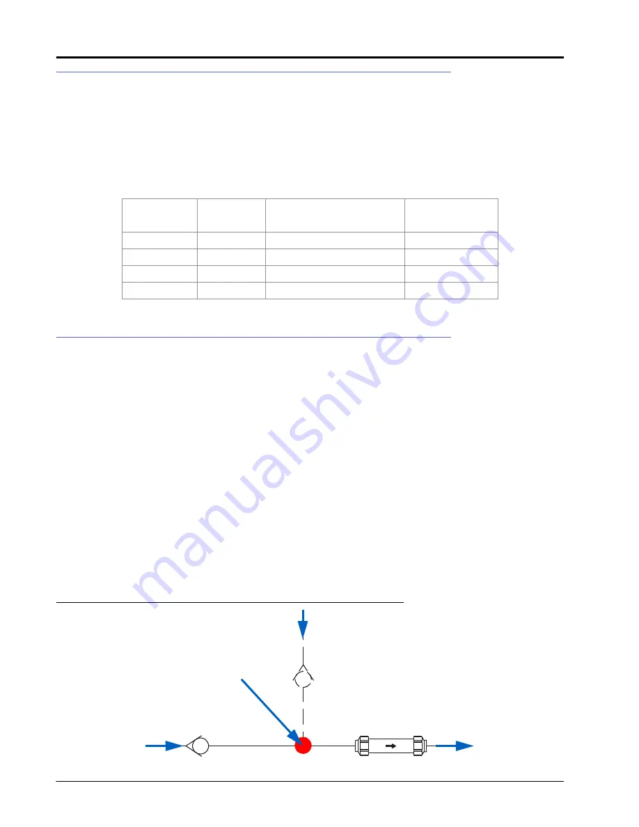
FIGURE 2. Point of Injection Detail
Agitator
Type
Blade Size
Tank
Part Number
Mix-All
3”
Non-Raven Tanks
910-0000-331
Mix-All
4”
Non-Raven Tanks
910-0000-341
Raven
3”
Raven 24 Gallon Tanks
117-0159-544
Raven
3”
Raven 50 Gallon Tanks
117-0171-655
From Carrier
Product Tank
To Boom Valve
Manifold
From
Injection
Module
Injection
Point Check
Valve
In-Line Mixer
Point of
Injection
Carrier
Check Valve


