Operation: Hawkeye Home Screen Definitions
49
OPERATION
turned on. For Hawkeye
®
HD mode, the rectangles represent the boom valve and nozzle control sections and the
rectangles will change color when the boom valve section is on.
NOTE:
Refer to Chapter 3, System Calibration, and restart the calibration wizard to configure implement
sections.
• Manually disabled sections will be displayed without a section status indicator below the section.
Sections enabled for product application will display a status below the section.
• Sections automatically controlled off according to task controller commands will display with an empty status
indicator. The task controller will automatically enable the section when the section returns to an unapplied
area in the field application.
• When the application system is enabled, the indicator for each section actively applying will be filled in. Task
controller may automatically shut off the section based upon the application coverage map.
ON-SCREEN MANUAL SECTION CONTROL
NOTE:
The on-screen manual section controls will only be
displayed if an optional Raven ISO Switch Box, or
another compatible switch interface, is not
available via the ISOBUS. If a switch box is detected,
use the switch box to control implement sections or
to enable the override feature. Review the Raven
ISOBUS Switch Box Operation Guide for additional
assistance with the Raven ISO Switch Box.
Use the manual section control buttons at the bottom of the Hawkeye
®
home screen to manually enable or
disable sections moving from left to right or from right to left depending upon the selection.
FOR EXAMPLE:
Select the disable option with the arrow pointing to the left to disable the first enabled sections, starting from
the right end of the implement width. Each time this disable option is selected, the next active section to the
left will be disabled, moving from right to left across the implement width.
To enable these sections again for application, touch the enable option with the arrow pointing right to re-
enable sections moving from left to right across the implement width, starting with the last section previously
disabled.
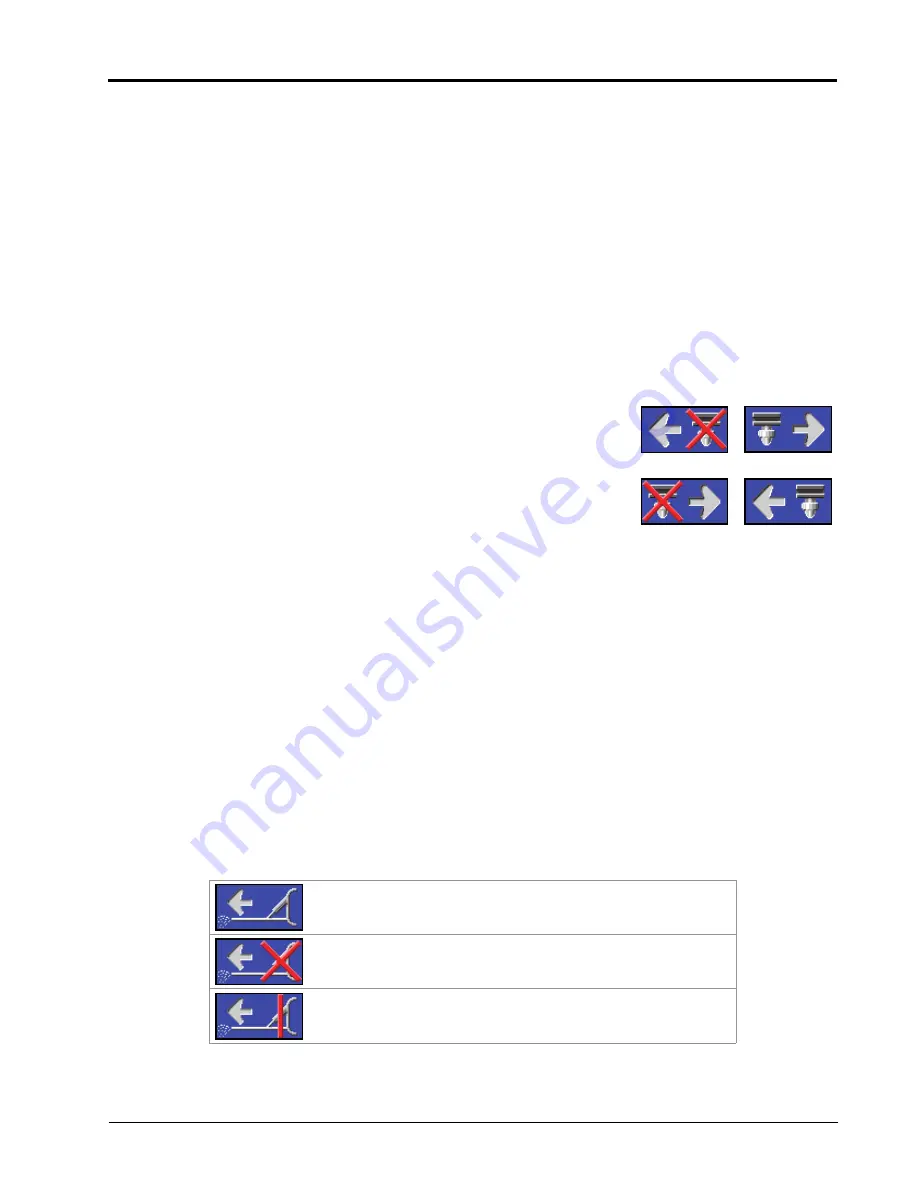
ON-SCREEN FENCE ROW STATUS AND CONTROL
If on-screen fence row control is enabled during the initial calibration wizard, the left and right fence row controls
will be available in the lower corners of the Hawkeye
®
main screen. The following status indicators may be
displayed on the home screen during operation:
On.
Fence rows are on and applying product.
Off.
Section switch assigned to fence row is off. Toggle the section
switch to enable application.
Master Off.
The section switch assigned to the fence row is on,
but the master switch is off. Toggle the master switch to enable
application.
Disable
Enable
Working from
the Right
Working from
the Left
Summary of Contents for ISO Product Controller II
Page 10: ...CHAPTER 1 viii ISO Product Controller II and Hawkeye Operation Manual...
Page 16: ...CHAPTER 1 6 ISO Product Controller II and Hawkeye Operation Manual...
Page 22: ...CHAPTER 2 12 ISO Product Controller II and Hawkeye Operation Manual...
Page 50: ...CHAPTER 4 40 ISO Product Controller II and Hawkeye Operation Manual...
Page 92: ...APPENDIX A 82 ISO Product Controller II and Hawkeye Operation Manual...
Page 95: ...P N 016 0171 584 H 85 FIGURE 3 Generic Cabling for Self Propelled Sprayer...
Page 97: ...P N 016 0171 584 H 87 FIGURE 5 Generic Cabling for Pull Type Sprayer with Existing Raven CAN...
Page 99: ...P N 016 0171 584 H 89 FIGURE 7 20 Spacing Generic Cabling...
Page 111: ...P N 016 0171 584 H 101...
Page 112: ...APPENDIX D 102 ISO Product Controller II and Hawkeye Operation Manual...
Page 116: ...APPENDIX E 106 ISO Product Controller II and Hawkeye Operation Manual...
Page 120: ...APPENDIX F 110 ISO Product Controller II and Hawkeye Operation Manual...
Page 128: ...APPENDIX G 118 ISO Product Controller II and Hawkeye Operation Manual...
Page 134: ...APPENDIX H 124 ISO Product Controller II and Hawkeye Operation Manual...


