background image

A-A

B-B

A

A

B

12

18

235

n

470

10

47

1

33,

5

9

11

n

518

n

462

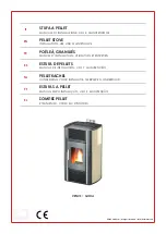
Viva 120 L Gas USA

A-A

B-B

A

A

B

12

18

235

n

470

10

47

1

33,

5

9

11

n

518

n

462

Summary of Contents for Viva 100 L Classic Gas

Page 1: ...1 POSITIV OUTLINE NEGATIV Installation Operation Manual RAIS VIVA L Direct Vent Gas Stove USA Canada...

Page 2: ...XPLOSION HAZARD Failure to follow safety warnings exactly could result in serious injury death or pro perty damage Do not store or use gasoline or other flammable vapors and liquids in the vicinity of...

Page 3: ...n pr fabriqu e mobile d j instal l e demeure si kes r glements locaux le permettent Cet appareil doit tre uniquement avec las type de gaz indiqu sur la plaque signal tique Cet appareil ne peut tre con...

Page 4: ...sic Gas without side glass Viva 100 LG Classic Gas with side glass Viva 120 L Gas without side glass Viva 120 LG Gas with side glass Viva 120 L Classic Gas without side glass Viva 120 LG Classic Gas w...

Page 5: ...RVICE 54 MAINTENANCE INSTRUCTIONS 55 ACCESSORIES 59 INSTALLATION OF MYFIRE WI FI BOX 60 SPARE PARTS LIST 62 FILL OUT THE INSTALLATION RECORD FORM IT CAN BE FOUND IN THE BACK OF THE MANUAL WE STRONGLY...

Page 6: ...LLATION MUST PROVIDE FOR ADEQUATE VENTILATION AIR TO THE APPLI ANCE THIS GAS APPLIANCE MUST NOT BE CONNECTED TO A CHIMNEY FLUE SERVING A SEPARATE SOLID FUEL BURNING APPLIANCE THE APPLIANCE WHEN INSTAL...

Page 7: ...BY A QUALIFIED SERVICE PERSON THE APPLIANCE SHOULD BE INSPECTED BEFORE USE AND AT LEAST ANNUALLY BY A PROFESSIONAL SERVICE PERSON MORE FREQUENT CLEANING MAY BE REQUIRED DUE TO EXCESSIVE LINT FROM CAR...

Page 8: ...RSONNE RISQU D AVOIR ACC S LA PI CE ET AUX SURFACES CHAUDES UN CRAN DESTINE R DUIRE LE RISQU DE BR LURE ATTRIBUTABLE LA VITRE CHAUDE EST FOURNI AVEC CET APPAREIL ET DEVRAIT TRE INSTALL POUR LA PROTECT...

Page 9: ...ter use The manual is necessary when the stove is to be serviced Ensure that the chimney terminal is not blocked in any way and is free of vegetation in the form of trees bushes etc and that objects a...

Page 10: ...rtant that you read the manual thoroughly before it is installed and put to use For the purpose of the guarantee and all contact regarding the stove in general it is important that you can state the s...

Page 11: ...s invalidated in the event of damage due to overfiring damage due to external influences and the use of unsuitable fuels failure to comply with statutory or recommended installation instructions and i...

Page 12: ...ecommended that the pilot flame be turned off if the appliance will not be in use for an extended period of time This appliance is equipped for use with the fuel type indicated on the rating plate Fue...

Page 13: ...that the gas supply and stove can be con nected Ventilation This stove has a sealed combustion chamber and is intended for a balanced draught There is therefore no need for an extra air supply It is r...

Page 14: ...e floor construction must be able to bear the weight of the stove and chimney if ap plicable If the existing design does not satisfy this prerequisite suitable measures must be taken e g a load distri...

Page 15: ...ity of the property owner to secure the services of qualified licensed professionals for the installation of hard wired carbon monoxide detectors In the event that the horizontally vented appliance is...

Page 16: ...0 feet 15m including vertical rise and horizontal run The vent lengths are measured from the stove not the floor The minimum vertical vent rise when using a vertical vent termination is 2 feet 600mm T...

Page 17: ...lue Horizontal Run 4 x6 5 8 Flue Feet metres Feet metres Feet metres 1 0 3 3 5 1 1 2 0 6 2 0 6 7 6 2 3 4 1 2 3 0 9 11 6 3 5 6 1 8 4 1 2 15 6 4 7 8 2 4 5 1 5 19 6 5 9 10 3 0 6 1 8 23 6 7 2 12 3 7 7 2 1...

Page 18: ...n Flue sizing VIVA L 4 x6 5 8 Connector on Appliance 4 x6 5 8 Maybe used Throughout Alternatively 5 x8 Expander may be used so that 5 x8 flue can be used thereafter Flue Terminal 4 x6 5 8 Alternativel...

Page 19: ...19 Vertical Roof Termination English RAIS User manual for VIVA L Gas...

Page 20: ...20 Vertical Roof Termination on angle English RAIS User manual for VIVA L Gas...

Page 21: ...21 Vertical Roof Termination with bends English RAIS User manual for VIVA L Gas...

Page 22: ...t of the ANSI standards and is based on testing conducted to determine where the exhaust gas temperature drops to the point where condensa tion might occur in the vent pipe The standards require the u...

Page 23: ...nlet to building or the com bustion air inlet to any other appliance 12 inches 30 cm 9 inches 23 cm K Clearance to a mechanical air supply inlet 6 feet 1 83 m 3 feet 91 cm above if within 10 feet 3 m...

Page 24: ...from the supply regulator to the area where the appliance is to be installed as per requirements outlined in the latest edition of the National Fuel Gas Code NFPA 54 USA or CAN CSA B1491 Canada Never...

Page 25: ...s being installed on a cement slab in cold climates a sheet of plywood or other raised platform can be placed underneath to prevent conduction of cold trans ferring to the fireplace and into the room...

Page 26: ...n the inner flange on the bottom surface of the stove And remove it 4 Unscrew the outer cover plate at the rear of the stove and move it to the upper sur face of the stove 5 To open the door a 10mm op...

Page 27: ...bottom The side pieces can then be removed 9 The back plate can now be removed and the inter nal cover plate dismounted 7 If the ceramic logs are fitted remove these 10 The internal cover plate is now...

Page 28: ...converted to bottled gas LPG The conversion must only be carried out by an author ised gas engineer Conversion kit Use article number 3713595 This set contains 4 new nozzles suitable for propane LPG g...

Page 29: ...L Gas The nozzle for the pilot light for LPG is marked 27 1 The nozzle for the pilot light for natural gas is marked 31 2 The nozzle for the main burner for LPG is marked 80 The nozzle for the main b...

Page 30: ...anual for VIVA L Gas The gas unit needs to be dismantled to gain access to the nozzles Do this in the following manner Lift the perforated plate up and out of the stove Loosen the four screws holding...

Page 31: ...ly pulling the pipe out Loosen the lock nut and then unscrew the nozzle Fit the LPG nozzle and tighten the lock nut Finally re tighten the coupling Once the gas unit has been dismounted replace the fo...

Page 32: ...ulling the pipe out and then unscrewing the noz zle Fit the LPG nozzle and tighten the lock nut Finally re tighten the coupling Replace the nozzle for the pilot light by loosening the coupling and car...

Page 33: ...rotating the air intake by 90 So that both holes in the vertical pipe are now open the small one at the rear and the large one at the front Small hole at the rear Large hole at the front The air inta...

Page 34: ...Gas The air intakes need to be reversed therefore when the stove is config ured for LPG The gas unit is reassembled using the four screws Replace the perforated plate and fully assemble the stove See...

Page 35: ...he burners are inserted above the pipes sticking through the perforated plate Note that there is a right burner and a left one so it is important that they are posi tioned as shown i e that the side w...

Page 36: ...and its thermosen sor are not covered over And that no glowing material finds its way down under the pilot plate guard The other thermosensor must also be kept free of the ceramic Embers When commiss...

Page 37: ...37 English RAIS User manual for VIVA L Gas ceramic Logs Log 1 Log 2 Log 3 Log 4 Log 5 Log 6 Log A Log B...

Page 38: ...s shown in the illustra tion Note The pilot area must be kept clear of Embers Position the 8 logs as shown Note the two special logs marked A and B have a groove moulded on their undersides that fits...

Page 39: ...39 English RAIS User manual for VIVA L Gas Log 4 Log 3 Log 5 Log 6 Log A Log B...

Page 40: ...f the box The receiver uses 4 x AA 1 5 V batteries Remember to replace the battery cover Start up Insertion of Batteries The receiver on the stove and the remote con trol use batteries A set of batter...

Page 41: ...41 English RAIS User manual for VIVA L Gas The batteries in the receiver must face the directions shown in the illustration The remote control uses 2 x AA 1 5 V batteries...

Page 42: ...he stove and remote control are synchronised in the following manner Press and hold down the Reset button until you hear a short beep followed by a long beep Release the button Now you have 20 seconds...

Page 43: ...e Knob 2 Open the Inlet pressure tap on the gas valve and connect a ma nometer 3 Check that the pressure measured concurs with the prescribed pres sure from the gas supply company 4 Carry out the test...

Page 44: ...44 English RAIS User manual for VIVA L Gas...

Page 45: ...from the stove s surface may occur during the initial ignition This is because the paintwork and ma terial need to harden but the smell will quickly disappear Ensure there is a lot of ventilation pref...

Page 46: ...teries of different makes If different batteries are used at the same time this could contribute to the battery overheating leaking and or exploding Software version Press on the and buttons at the sa...

Page 47: ...t minutes by pressing on the or button 7 This is confirmed by pressing the and buttons at the same time or waiting Change between C and F by pressing and holding the and buttons at the same time NOTE...

Page 48: ...time until you hear a short beep and a se ries of flashing lines confirm that the start sequence has commenced Then release the buttons The main gas supply starts as soon as pilot ignition is confirm...

Page 49: ...compared to the temperature set The flame height is then adjusted automatically to reach the temperature set Program mode PROGRAMS 1 and 2 can both be programmed to start or stop at specific times at...

Page 50: ...d ALL is displayed briefly and HOUR flashes 13 Select hour by pressing on the or button 14 This is confirmed by pressing on the button 1 OFF is displayed ALL is displayed briefly and Min utes flashes...

Page 51: ...individual weekday for several week days or for all days of the week Wait until set up is complete HELP MODE After ignition burner 1 is ignited and burner 2 is in the last setting ON A burner is igni...

Page 52: ...amber Turn the gas valve clockwise to OFF Turn the button for manual control over to man Turn on the gas for the pilot flame by pressing and holding the Pilot gas valve down with a pointed object Igni...

Page 53: ...ed by turn ing the gas valve anticlockwise above to 2 ON The gas valve should be fully open for a minimum of 30 seconds before the flames are turned down When the correct setting is reached the door c...

Page 54: ...rners Lift out the perforated sheet 5 Vacuum the entire burner 6 Clean the pilot burner joint with a soft brush and a vacuum cleaner The thermosensors must not be bent or adjusted 7 Put on the gas sup...

Page 55: ...hat a qualified service technician perform an appliance check up service once a year Any safety screen or guard removed for servicing MUST BE REPLACED before operating this appliance DO NOT USE this a...

Page 56: ...nd any lint or foreign material must be removed with a brush or vacuum Thermocouple Maintenance The thermocouple completeness and operation must be checked The qualified engineer must confirm that the...

Page 57: ...used to clean the metal parts of the firebox Replace the logs and embers after cleaning MAINTENANCE LOG Date of Service __________________ Serviced By ______________________ Service Performed Inspect...

Page 58: ...parts carefully with a soft brush and a vacuum cleaner Only replace damaged parts with original Rais specified parts Pack scrap ceramics in plastic bags and deliver to the correct waste locations It...

Page 59: ...or Viva 120 L 4 in a set 2710611SV Stainless Classic Top plate for Rear outlet 2710612SV Stainless Classic Top plate for Top outlet 3713506 Mains Adapter Connecting the stove to a network 3713507 MyFi...

Page 60: ...on chamber by opening the stove door and inserting the narrow plug on the Wi Fi lead into the opening marked SI The wide plug on the Wi Fi lead is inserted into the Wi Fi box When connecting the Wi Fi...

Page 61: ...o the Wi Fi router home network you need to ensure That a home network is available That the name and access code of the home network are correct That the Wi Fi router s SSID key is not hidden That th...

Page 62: ...parts from your RAIS dealer See spare part drawings back of the manual xx optional colour code Pos Number Article no Description 1 1 37120xx Glass door 2 1 37121xx Classic Glass door 3 1 2710601xx To...

Page 63: ...ption 1 1 37120xx Glass door 2 1 37121xx Classic Glass door 3 1 2710601xx Top plate for rear outlet 4 1 2710602xx Top plate for top outlet 5 1 2720601xx Top plate for rear outlet Embossed 6 1 2720602x...

Page 64: ...r Top Assembly Front 12 RA10L76 Burner Raised Assembly Left 13 RA10R76 Burner Raised Assembly Right 14 RK10P07 Complete Burner Assembly Natural RK10N07 Complete Burner Assembly LPG 15 RK10 SEAL 05 Bur...

Page 65: ...65 Fran ais English RAIS User manual for VIVA L Gas...

Page 66: ...A A B B A B B 1000 n470 n518 n 4 6 2 967 I 133 5 L 831 J 235 M Viva 100 L Gas USA A A B B A B B 1000 n470 n518 n 4 6 2 967 I 133 5 L 831 J 235 M...

Page 67: ...A A B B A A B 1218 235 M n470 1047 I 133 5 L 911 J n518 n462 Viva 120 L Gas USA A A B B A A B 1218 235 M n470 1047 I 133 5 L 911 J n518 n462...

Page 68: ...Viva 160 L Gas USA A A B B A A B 1618 235 M n470 1107 I 133 5 L 971 J n518 n462 A A B B A A B 1618 235 M n470 1107 I 133 5 L 971 J n518 n462...

Page 69: ...7 8 3 4 5 6 1 2 9 Viva 100 L Gas Viva 120 L Gas Viva 160 L Gas...

Page 70: ...70 7 8 9 10 13 15 14 12 11 3 4 5 6 2 1 16 Viva 100 L G Gas Viva 120 L G Gas Viva 160 L G Gas...

Page 71: ...r stove The installer should keep a duplicate of this form for their records DATE PURCHASED DEALER INSTALLER STOVE SERIAL NUMBER DATE INSTALLED FUEL NAT GAS LP GAS INLET PRESSURE MEASURED AFTER INSTAL...

Page 72: ...RAIS A S Industrivej 20 DK 9900 Frederikshavn Denmark www rais dk...

Reviews: