background image

COMPUTER INTERFACE FOR TOXIRAE 

5 - 22 


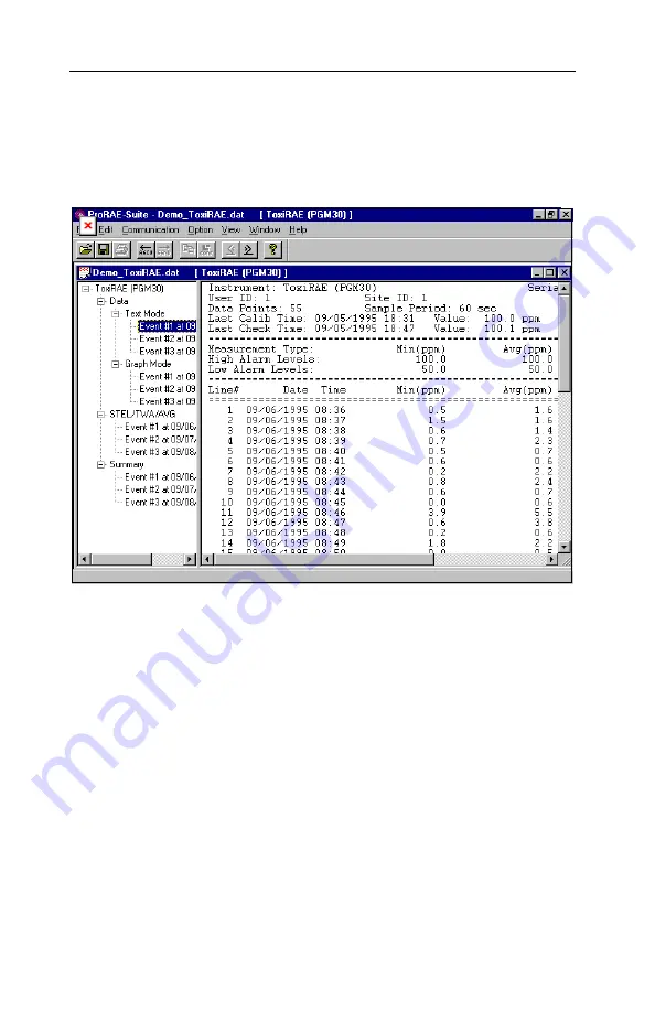
5.6.2   View Logged Data in Text Mode 

Once the user opens a data file or receives the logged data 
from the instrument, a data window appears, as shown in 
Figure 5.9. 


Figure 5.9   Displayed Logged Data 

 
The data window is a two-pane client window.  The left 
pane is a tree view that lists all the display format of each 
event, and the right pane displays the information 
according to the display format and the event the user 
selected on the left pane.  To select any display format of 
any event, the user can simply click the format item on 
the left pane.  To view the next event or the previous 
event, the user can click the 

Next Event

 (double right 

arrow) or the 

Previous Event

 (double left arrow) toolbar 

buttons.  The user can also drag the splitter bar between 

Summary of Contents for ToxiRAE PGM-30

Page 1: ...ToxiRAE POCKET PID PGM 30 OPERATION AND MAINTENANCE MANUAL Document No 007 4001 004 Rev E RAE SYSTEMS INC 3775 N First St San Jose CA 95134 1708 May 2005...

Page 2: ...itors UltraRAE Specific Compound Monitors ToxiRAE PLUS PID Monitors ToxiRAE PLUS Single Gas Monitors ToxiRAE PLUS Oxygen Monitors ToxiRAE PLUS Combustible Monitors ModuRAE Fixed System PID MiniRAE PLU...

Page 3: ...ToxiRAE PID PGM 30 requires the new lamp so when ordering replacement lamps please use part 050 0040 000 The ToxiRAE PID PGM 30 with firmware version V1 27 and below requires the standard lamp please...

Page 4: ...ration of ToxiRAE Unit 4 7 4 4 1 Zero Gas Calibration 4 8 4 4 2 Standard Reference Gas Span Gas Calibration 4 10 4 4 3 Standard Reference Gas Span Gas Check 4 12 4 4 4 Enter Standard Calibration Gas V...

Page 5: ...in Text Mode 5 22 5 6 3 View STEL TWA AVG Value 5 24 5 6 4 View Summary Information 5 25 5 6 5 View Logged Data in Graph Mode 5 26 5 6 6 Export the Displayed Data to a Text File 5 30 5 6 7 Exporting...

Page 6: ...sed maintained and serviced in accordance with the manufacturer s instructions CAUTION TO REDUCE THE RISK OF ELECTRIC SHOCK TURN OFF POWER BEFORE REMOVING THE SENSOR CAP AND SENSOR MODULE FOR SERVICE...

Page 7: ...attery packs part nos 500 0021 or 500 0022 This instrument has not been tested in an explosive gas air atmosphere having an oxygen concentration greater than 21 Substitution of components may impair i...

Page 8: ...to known concentration calibration gas before each day s use AVERTISSEMENT La calibration de toute instruments de RAE Systems doivent tre test en exposant l instrument a une concentration de gaz conn...

Page 9: ...for several minutes the residual vapor in the sensor chamber will be cleared and the reading should return to zero 2 The battery of the ToxiRAE unit will discharge slowly even if it is turned off If t...

Page 10: ...plied 10 6 eV gas discharge lamp and 2 chlorinated compounds with the interchangeable 11 7 eV lamp available as an optional accessory Features are Lightweight and Compact 6 4 oz pocket size Dependable...

Page 11: ...chamber Battery Rechargeable 2 4V 900 mAh Ni CD battery pack or alkaline battery adapter Operating Time 12 hours continuous operation Attachment Belt Pocket clip Display 8 digit LCD with LED backligh...

Page 12: ...buzzer and flashing red LED to indicate exceeded preset limits low battery or lamp failure Calibration Two point field calibration for zero gas and standard reference gas Protection Password protected...

Page 13: ...arge a ToxiRAE Pocket PID plus 1 auxiliary connector to charge a spare Ni Cd battery pack Power Source 110VAC or 6V DC Charging Time 4 hours to full charge Charge Status Three color LED to indicate ch...

Page 14: ...and activates alarm signals whenever the exposure exceeds preset limits Prior to factory shipment the ToxiRAE is preset with default alarm limits and the sensor is pre calibrated with 100 ppm isobutyl...

Page 15: ...ng keys for normal operation or programming of the unit LCD display with back light to show real time and calculated measurements Buzzer and red LED for alarm signal whenever the exposures exceed pres...

Page 16: ...OPERATION OF TOXIRAE 2 3 Figure 2 1 Major Parts of the ToxiRAE Pocket PID Unit...

Page 17: ...xiRAE Pocket PID Unit Table 2 1 Key Function in Normal Operation MODE Turn on off the power and choose different display mode N Toggle on off the back light Y Alarm test and alarm acknowledge turn off...

Page 18: ...ntration in ppm Time weighted average TWA value of the gas concentration in ppm Short term exposure level STEL of the gas concentration in ppm Peak gas concentration in ppm Battery voltage in volts Ru...

Page 19: ...four preset alarm limits battery voltage and available data storage memory in percentage After about 20 seconds the display shows the instantaneous reading of the gas concentration in ppm and is ready...

Page 20: ...e is a letter D follows the version number indicates that the unit is configured as a Datalog unit Without the letter D it is a Non Datalog unit User can upgrade a Non Datalog unit to a Datalog unit C...

Page 21: ...r million ppm The reading is updated once per second and is shown as nn n ppm in the LCD display 2 The TWA reading is the accumulated reading of the gas concentration divided by 8 hours since the unit...

Page 22: ...minute interval and is shown as Run Time and nn nn on the LCD display 7 The Log On Off menu prompts the user to turn on or off datalogging To turn on datalogging press the Y key while Log On is displ...

Page 23: ...o choose a display These eight displays are arranged in a round robin order instantaneous TWA STEL Peak battery voltage Run time Log On Off PC comm instantaneous To choose a specific display press the...

Page 24: ...level 2 2 V UV lamp or the sensor module fails or datalog memory is full the unit also activates the buzzer and red LED When the low battery alarm occurs there is approximately 20 30 minutes of opera...

Page 25: ...tion 5 0 for details on how to set alarm mode Alarm Signal Summary The various alarm signals are summarized here Condition Alarm Signal Gas exceeds Hi Alarm limit 3 beeps flashes per second Gas exceed...

Page 26: ...momentarily The buzzer will beep and the LED and backlight will flash once to indicate that these alarm signals are functioning correctly WARNING THE ALARM SIGNALS ARE DISABLED DURING PC COMMUNICATIO...

Page 27: ...onditions Pressing and holding the N key for one second in normal operation can turn on this backlight Pressing the N key a second time turns off the backlight Note The LED backlight consumes a higher...

Page 28: ...and is programmed with default alarm limits as listed below Refer to Section 4 for programming procedures if new calibration or alarm limits are required Table 2 2 Factory Calibration and Preset Alar...

Page 29: ...ID a site number serial number last calibration and check date and alarm limits are also stored All data is retained in non volatile memory so it can be down loaded at a later time to a PC even if th...

Page 30: ...us All other modes of datalogging will start and stop automatically without any user intervention Automatic Datalogging Datalogging is automatically started at the end of each datalogging period when...

Page 31: ...he following conditions the datalogging will be paused automatically 1 When entering programming mode datalogging will stop Upon exiting the programming mode the datalogging will resume 2 When enterin...

Page 32: ...cket PID An AC to 6V DC wall mount adapter for 110 V AC power source Tri colored LED for charging status indication of the charger Red battery is being charged Green charging is completed Amber batter...

Page 33: ...OPERATION OF CHARGING STATION 3 2 Figure 3 1 Single Unit Charging Station...

Page 34: ...into the small jack on the back of the station 4 The LED should be red in color when charging If the battery is fully charged the LED will change from red to green The red color indicates that the bat...

Page 35: ...new battery under the best condition As the battery becomes older or is subject to adverse conditions the battery capacity will be reduced significantly Charger Time Out The battery charger has a buil...

Page 36: ...tation provides a means to manually discharge the Ni CD battery Inside the opening of the charger near one corner of the bottom plate there is a small hole Insert a pencil or ball point pen to press a...

Page 37: ...ration The adapter is intended for use in emergency situations when there is no time to charge the Ni Cd battery The charging station is designed to prevent damage to alkaline batteries and the chargi...

Page 38: ...riven to provide intuitive end use operation The display shows the menu options and the keypad is used for menu selection and data entry Note The real time monitoring of the gas concentration continue...

Page 39: ...iewed by pressing the N repeatedly until the desired option is displayed To enter a particular menu press Y key the sub menu will be displayed To exit the programming mode press the MODE key at any of...

Page 40: ...nst un unauthorized changes to the instrument alarm settings and other settings The level 2 security allows a user to enter programming mode without any password checking This is the default security...

Page 41: ...e programming mode as summarized below Table 4 2 Key Function in Programming Mode MODE Exit menu when press momentarily or exit data entry mode when pressed and held for 1 second Y Increase numerical...

Page 42: ...nter the programming mode and the first menu item Calib will be displayed If the user mode is display the unit will show Display and return to normal display of instantaneous readings 4 If the securit...

Page 43: ...ws the actual digit entered and moves the flashing cursor to the next digit to the right 6 Repeat Step 4 until all four digits are entered Press and hold MODE key for one second 7 If the entered passw...

Page 44: ...ing mode the user may re calibrate the ToxiRAE Unit This is a two point calibration process using zero gas and the standard reference gas First a zero gas which contains no detectable organic gases or...

Page 45: ...tional are required The zero air is clean dry air without any organic vapor or impurities If such an air bottle is not available any clean ambient air without detectable contaminant can also be used A...

Page 46: ...free of any detectable vapor do not use calibration adapter in the latter case 3 Press Y key to zero the unit The display shows zero After about 2 seconds the display should shows reading of 0 0 OK 4...

Page 47: ...urn on the valve of the gas bottle to start the flow of span gas Then press Y key Display shows Wait for about 30 seconds while the instrument performs calibration Afterward the display shows 100 0 OK...

Page 48: ...e ToxiRAE Unit Ensure that the sensor cap is still firmly secured onto the PID unit 5 Press the MODE key to exit the calibration sub menu and move directly to next menu item Set Alarm Limits shown in...

Page 49: ...2 Turn on the valve of the gas bottle to start the flow of span gas Then press Y key Display shows Wait for about 5 seconds Afterward the display should show 100 0 OK Note The reading should be close...

Page 50: ...still firmly secured onto the PID unit 5 Press the MODE key to exit the calibration sub menu and move directly to next menu item Set Alarm Limits shown in Table 4 1 Note When span check is performed a...

Page 51: ...2 Display shows Cal Gas 2 Press Y key Display shows Cal Gas and 100 0 which means that the previous calibration gas value is 100 ppm If the concentration of the new calibration gas to be used is diffe...

Page 52: ...git the flashing digit will move to next digit to the right Repeat this process until all 4 digits are entered Press and hold the MODE for 1 second to enter the new calibration gas value 4 The display...

Page 53: ...various alarm limits for the ToxiRAE Unit Table 4 3 shows the sub menus for setting alarm limits default limits shown Table 4 3 Sub Menu Option Display 1 Set TWA alarm limit TWA 0010 0 2 Set STEL alar...

Page 54: ...ily to advance to next digit The flashing digit will move on to next digit to its right Repeat this process until all 4 digits of the new TWA alarm limit are entered Press and hold the MODE key for 1...

Page 55: ...ily to advance to the next digit The flashing digit will move on to next digit to its right Repeat this process until all 4 digits of the new STEL alarm limit are entered Press and hold the MODE key f...

Page 56: ...omentarily to advance to the next digit The flashing digit will move on to next digit to its right Repeat this process until all 4 digits of the new Lo Alarm limit are entered Press and hold MODE key...

Page 57: ...o advance to the next digit The flashing digit will move on to next digit to its right Repeat this process until all 4 digits of the new Hi Alarm limit are entered Press and hold the MODE key for 1 se...

Page 58: ...d interval or period More datalogging options can be programmed in the PC and downloaded to the unit see Section 5 0 for details on how to program various datalogging options Table 4 4 shows the two s...

Page 59: ...data memory is the first sub menu item in Table 4 4 Display shows Clear message 2 Press the Y key to clear the data memory Display shows Sure to re confirm the clearing of memory 3 Press the Y key ag...

Page 60: ...se the Y or N key to change the digit value and press the MODE key momentarily to advance to the next digit The flashing digit will move to the next digit to the right Repeat this process until all 4...

Page 61: ...y change the year month date hour and minute of the real time clock inside the ToxiRAE Unit Table 4 5 shows the sub menus for setting real time clock Table 4 5 Sub Menu Option Display 1 Set year Year...

Page 62: ...digit The flashing digit will move on to next digit to its right Repeat this process until both digits of the new year value are entered Press and hold the MODE key for 1 second to exit data entry mo...

Page 63: ...xt digit The flashing digit will move on to next digit to its right Repeat this process until both digits of the new month value are entered Press and hold the MODE key for 1 second to exit data entry...

Page 64: ...digit The flashing digit will move on to next digit to its right Repeat this process until both digits of the new date value are entered Press and hold the MODE key for 1 second to exit data entry mod...

Page 65: ...ance to the next digit The flashing digit will move on to next digit to its right Repeat this process until both digits of the new hour value are entered Press and hold the MODE key for 1 second to ex...

Page 66: ...igit The flashing digit will move on to next digit to its right Repeat this process until both digits of the new minute value are entered Press and hold the MODE key for 1 second to exit data entry mo...

Page 67: ...a different gas during calibration ToxiRAE Unit can store four sets of correction factors for different gases including the calibration gas From a PC the user can choose 4 gases from a list of over 4...

Page 68: ...message where Hexane is the previously selected gas 2 Press the Y key to accept the current gas selection Display shows Hexane loaded and move to next sub menu item Or press the N key to see next avai...

Page 69: ...e left most digit use the Y or N key to change the digit value and press the MODE key momentarily to advance to the next digit The flashing digit will move on to next digit to its right Repeat this pr...

Page 70: ...ode users may change the user ID or site number so that datalogging will include appropriate user and site information Table 4 7 shows the two sub menus for setting up the instrument Table 4 7 Sub Men...

Page 71: ...to change the digit value and press the MODE key momentarily to advance to the next digit The flashing digit will move on to next digit to its right Repeat this process until all four digits of the n...

Page 72: ...he Y or N key to change the digit value and press the MODE key momentarily to advance to the next digit The flashing digit will move on to next digit to its right Repeat this process until all four di...

Page 73: ...ble 4 1 press the MODE key once Display shows an instantaneous reading of normal operation mode 2 To exit programming mode from sub menu level see Table 4 2 4 7 press the MODE key twice 2 To return to...

Page 74: ...ter PC under Windows 95 Windows 98 Windows NT 4 0 and later environments It allows the user to configure the ToxiRAE through a user friendly interface and send the configuration information from the P...

Page 75: ...en field as shown in Figure 5 1 Figure 5 1 Run Dialog Box Press the Enter key on the keyboard or click the OK button on the Run datalog box to start the setup process If the user chooses the default s...

Page 76: ...item to display the ProRAE Suite submenu There are two submenu items under the ProRAE Suite submenu ProRAE Suite and Readme as shown in Figure 5 2 Click the ProRAE Suite submenu item to start the ProR...

Page 77: ...E monitor is ready and waiting for communication with PC During the communication session the PC will directly control the ToxiRAE monitor through the serial link There is no need for users to press a...

Page 78: ...hows the main window of the ProRAE Suite software Figure 5 3 ProRAE Suite Main Window The functions of ProRAE Suite software can be divided into three categories 1 Configuration data category This cat...

Page 79: ...resented in this tool bar in the form of a small icon For example the Receive data function in the Communication sub menu is represented as a small arrow with the letters RECV When the mouse cursor a...

Page 80: ...rding to the PC s serial port setup Figure 5 4 Setup Port Dialog Note In most PC s there are two serial ports Make sure that the serial port selected in the Setup Port dialog box matches the actual se...

Page 81: ...guration Data The ProRAE Suite software allows user to edit the configuration data send the configuration data to the ToxiRAE monitor and receive the configuration data from the ToxiRAE monitor The fo...

Page 82: ...g Box There should be one or more configuration files in the file list Each configuration file has a file extension of CFG There is one generic ToxiRAE configuration file supplied with ProRAE Suite so...

Page 83: ...ata To edit the opened configuration data file click the Edit Configuration menu item or the Configuration toolbar button to open the Edit Configuration File dialog box as shown in Figure 5 7 After fi...

Page 84: ...he description of each field in the General tab page of the Edit Configuration File dialog ID This section sets the identification that is used throughout the datalog process Both editing fields Site...

Page 85: ...the programming menu requires the four digit password be punched in if Level 1 is selected as the security level User mode In the Display mode the user can view several readings in the normal operatio...

Page 86: ...values or any combinations of the three values Datalog Interval The datalog interval is the rate at which datalog samples are recorded while the datalog is running The unit of datalog interval is sec...

Page 87: ...tomatically Start Time and Stop Time If scheduled start stop mode is chosen for datalogging all entry boxes must be completed for start and stop year month day hour and minute The monitor must already...

Page 88: ...el ppm and high alarm level for the sensor Calibration Span ppm The user can specify the calibration gas span for the sensor here Current Gas Selection This is the place where the user can choose a se...

Page 89: ...FOR TOXIRAE 5 16 OK Cancel When the configuration changes are completed click on the OK button to save the configuration and return to the client window or click on the Cancel button to abort the con...

Page 90: ...er making sure that the instrument is connected to the PC click the OK button to start the data transfer After the configuration information is sent successfully a message box will appear to indicate...

Page 91: ...instrument is connected to the PC click the OK button to start the data transfer After the data transfer is finished a new client window is opened with the newly received configuration data displayed...

Page 92: ...ill erase all the current configuration settings in the monitor If the user does not want this to happen click the Cancel button otherwise click the OK button to start the data transfer After the info...

Page 93: ...ata The ProRAE Suite software allows the user to retrieve the logged data from the ToxiRAE monitor and display the data in many different formats The user can also export the displayed text to a tab d...

Page 94: ...appear to remind user to connect the instrument to the PC through the serial port After making sure the instrument is connected to the PC click the OK button to start the data transfer After the data...

Page 95: ...s a tree view that lists all the display format of each event and the right pane displays the information according to the display format and the event the user selected on the left pane To select any...

Page 96: ...he right to enlarge a pane as desired To view the data points of a specific event the user can click the item representing that event under the item Text Mode For example click the item Event 1 on the...

Page 97: ...ew the STEL TWA or AVG value of any event click the event number item under the tree item STEL TWA AVG in the left pane The right pane displays the STEL TWA and AVG value of each data point of that ev...

Page 98: ...summary information of any event such as peak value and minimum value click the event number item under the tree item Summary in the left pane The right pane displays the summary information of that e...

Page 99: ...t event as shown in Figure 5 12 Figure 5 12 Graph of the Logged Data Select graph type The user can choose the type of data in the Graph Type tab page of the Graph Settings dialog box To display the G...

Page 100: ...h Settings dialog box click any place in the right pane so that pane has the focus then click Option Graph Settings menu item to display the Graph Settings dialog box To bring the Graph Range tab page...

Page 101: ...e Y axis group box If the user selects the Default radio button in the Y Axis Data Value Range type group box the ProRAE Suite software will scale the range of Y axis by itself to cover the maximum da...

Page 102: ...R INTERFACE FOR TOXIRAE 5 29 If the Default radio button is selected in the X Axis Data Time Range group box the ProRAE Suite will scale the range of X axis by itself to cover the every data point on...

Page 103: ...er to export the displayed text to a tab delimited text file so that Microsoft Excel can read it directly To export the text displayed in the right pane to a tab delimited text file click Option Expor...

Page 104: ...o a windows bitmap or metafile file first click any place in the right pane to make sure that the graph pane has the focus then click Option Export Graph menu item to display a Save As dialog box Sele...

Page 105: ...of the text or graphic data report First click any place in the right pane to set the focus on that pane then select the File Print menu item or click the Print toolbar button a printer to print the...

Page 106: ...en as shown in Figure 5 15 Figure 5 15 Main Window of ProRAE Suite Click Option Enable Datalog menu item and a message box will appear to remind the user to connect the instrument to the PC through th...

Page 107: ...bled If the user wants to enable the datalog option click Enable radio button and type the three digit authorization code in the Authorization Code field then click the OK button to close the dialog b...

Page 108: ...lamp as the high energy photon source for the PID instrument A special high efficiency lamp driver is developed to turn on the UV lamp see Figure 6 1 micro computer driver UV lamp LCD display keypad...

Page 109: ...r for faster instrument response A single chip microcomputer is used to control the operation of the lamp alarm buzzer LED power supply and the electrometer It measures the electrometer readings and c...

Page 110: ...MAINTENANCE 7 1 7 MAINTENANCE As shown in Figure 7 1 the major maintenance items of a ToxiRAE PLUS are Battery Pack Sensor Module Lamp Figure 7 1 Main Components of ToxiRAE...

Page 111: ...work A fully charged battery powers a ToxiRAE unit for 12 hours continuous operation The charging time is less than 4 hours for a fully discharged battery The charging station is controlled by two ste...

Page 112: ...here is still no LED light it indicates a bad contact or defective battery pack Replacing and Recharging Battery Pack 1 Turn off power of the Pocket PID unit 2 Refer to Figure 7 1 unscrew the sensor c...

Page 113: ...g Alkaline Battery Adapter 1 Insert two fresh AAA size alkaline batteries into the adapter Make sure that the polarity of the battery is observed 2 Follow the same procedure as described above to repl...

Page 114: ...s a static shield for the sensor This filter needs to be cleaned when it is dirty The sensor module is made of several components and is attached to the lamp housing unit as shown in Figure 7 1 Sensor...

Page 115: ...ule and the filter 8 Make sure that the sensor module and filter is fully dried before it is put back into the instrument 9 Refer to Figure 7 1 insert the sensor module and filter into the lamp housin...

Page 116: ...not damaged 1 Turn off power of Pocket PID Unit 2 Refer to Figure 7 1 unscrew the sensor cap Remove the sensor module and filter 3 Gently pull out the lamp avoiding contact with the flat window surfa...

Page 117: ...b in a circular motion at moderate pressure After cleaning hold the lamp up to the light at an angle to detect any remaining film Repeat the process until the lamp window is clean Never touch the wind...

Page 118: ...place the unit into the special diagnostic mode first turn the unit off Next push and hold the Y key while still holding the Y key also push and hold the MODE key for at least two seconds After the r...

Page 119: ...mp failure level may be set too high This level can be adjusted using the following steps 1 Turn the unit off 2 Remove the lamp 3 Turn on the unit in the special diagnostic mode 4 Push the MODE key un...

Page 120: ...ive battery Microcomputer hang up Solutions Charge or replace battery Disconnect then connect battery to reset computer No LED or LCD back light Reasons Defective LED or LCD back light Solutions Call...

Page 121: ...rty sensor Weak or defective lamp Defective pump Fan Solutions Clean sensor Clean or replace lamp Replace lamp housing with pump Note ToxiRAE PGM 30 with firmware V1 30 and above requires replacement...

Page 122: ...y Reasons Incorrect gas calibration Low sensitivity to cal gas Solutions Calibrate the unit Use different cal gas Cannot turn off unit or corrupted characters in LCD display Reasons Microprocessor han...

Page 123: ...asons Dirty or wet sensor Solutions Clean and dry sensor Replace filter Measurement max out at certain level Reasons Dirty lamp sensor module Weak lamp Solutions Clean lamp sensor module Replace new l...

Page 124: ...ENCE OF DISPLAY MODE Instantaneous TWA STEL Peak Battery volt Run Time m m m m m m Toggle N m for 3 seconds Log On Off PC comm m m Beep Flash Y Ready Y m or N N Back Light Toggle Manual Y Datalog Prog...

Page 125: ...STEL 0 0 STEL reading ppm MODE Peak 0 0 Peak reading ppm MODE Bat 2 5 V battery voltage volt MODE Run Time 0 30 Run time hour minute MODE Log On Off Enable or disable datalogging Y start stop datalog...

Page 126: ...B 1 APPENDIX B QUICK REFERENCE OF PROGRAM MODE Calib Alarm Data Clock Gas Setup N N N N N N Zero Y Span N Check N Cal Gas N m TWA Y STEL m Lo m Hi m m Clear Y Period N m Year Y Month m Date m Hour m m...

Page 127: ...t the value N Cal Gas edit calibration gas value Y Cal Gas 100 0 enter cal gas value Y TWA 01 0 enter TWA limit MODE STEL 02 0 enter STEL limit MODE Lo Alarm 10 0enter Lo Alarm limit MODE Hi Alarm 10...

Page 128: ...for the 10 6 eV lamp Table C 1 Compound Correction Factor Acetaldehyde 5 5 Acetone 1 1 Allyl alcohol 2 4 Benzene 0 53 Butadiene 1 0 Butyl acetate 2 6 Carbon disulfide 1 2 Cyclohexane 1 4 Cyclohexanon...

Page 129: ...hylene 0 58 Pinene a 0 31 Pinene b 0 37 Propylene 1 7 Styrene 0 42 Tetrahydrofuran 1 8 Toluene 0 50 Trichloroethylene 0 52 Vinyl chloride 2 14 Xylene m 0 43 Xylene o 0 59 Xylene p 0 45 The calibration...

Page 130: ...MiniRAE PLUS PGM 76 and 76IS ProRAE 76 Software Upgrade for PGM 75 TN 109 MiniRAE Professional PID Zero Drift TN 112 MiniRAE PLUS Datalogger Data Conversion to Microsoft Excel version 5 0 TN 113 Calib...

Page 131: ...RAE PID TN 126 Interchangeability of Sensors in PGM 35 and PGM 50 TN 127 Benzene Specific Measurements in Petroleum Hydrocarbons using the UltraRAE TN 128 ToxiRAE PID Communications Problems TN 129 Ga...

Page 132: ...AE Communication with NT TN 140 Tubing Volume TN 141 MultiRAE Remote Control TN 142 MiniRAE 2000 Compound Library TN 143 Tube Accuracy Comparison TN 144 LEL Sensor Poisoning TN 145 Ni Cd Maintenance T...

Page 133: ...UltraRAE User List AP 210 North American RAE Instrument User List AP 211 PIDs for Continuous Monitoring of VOCs AP 212 PIDs for Indoor Air Quality AP 213 ModuRAE PID Configuration and Applications AP...

Page 134: ...APPENDIX E RAE SYSTEMS APPLICATION NOTES E 2 See Appendix F on how to obtain Application Notes...

Page 135: ...to Attn Literature Department 1 408 952 8480 FAX Please send me the following information Name Company Mailing Address City State Zip Country Telephone Fax Technical Notes just list TN Application Not...

Page 136: ...tain the following information in full Name Company Shipping Address City State Zip Telephone Fax Serial number Model Reason for return Note When returning an instrument for repair please send only th...

Page 137: ...ctive part if returned to a RAE authorized factory repair center with shipping charges prepaid by the buyer and which upon inspection by RAE shall prove to have been defective in normal use and servic...

Page 138: ...ducts THIS EXPRESS WARRANTY SHALL EXTEND TO BUYER OF RECORD ONLY AND NOT TO SALES MADE BY BUYER S CUSTOMERS EXCEPT FOR THE WARRANTY OF TITLE THE FOREGOING EXPRESS WARRANTY IS IN LIEU OF ANY AND ALL OT...

Page 139: ...oll Free Numbers Instrument Sales 877 RAE CUSTomer 723 2878 Technical Service 888 RAE 4800 723 4800 Tube Sales 888 RAE TUBE 723 8823 E mail Instrument Sales raesales raesystems com Technical Service t...

Reviews: