Installation Manual
Combi - cod. 99943NA – November 2002
14
TECHNICAL DATA
DIFFERENTIAL AIR PRESSURE SWITCH FOR FAN CONTROL
To guarantee maximum safety in flue exhaust, a differential pressure switch is
installed on the Room Sealed Combustion Chamber Model (wall-mounted, room-
sealed boilers) and on forced draught boilers. This pressure switch automatically
controls perfect functioning of the fan and the passage of both external air and
exhaust flue pipes.
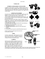
DIVERTER VALVE VC 6012MG6000
The diverter valve is the device which controls the boiler switching from central
heating to d.h. water circuit and vice versa. The diverter valve is
fitted with a manual command lever
L
(see fig. 2) which, when set
on the top position, towards the valve head, allows the boiler operating on the
domestic hot water circuit while, when set on the low position, the boiler operates
on the central heating circuit.
When the
L
lever is set on the central position, it allows the actuator on midway.
In this position,
to be used only in case of motor failure or damage
, both central
heating and domestic hot water ports are open and both domestic hot water and
central heating circuits are operating.
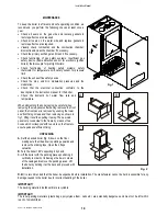
For restore the initial position, separate the actuator and the valve body following
instructions from no.1 to no.4 (see fig.1).
To separate the motor from the valve body proceed as follows:
1.
Press button
A
under the motor.
2.
Simultaneously keep the
A
button pressed and turn the actuator counter-
clockwise;
3.
Lift off the motor
4.
To disconnect the power supply cable press the
B
tap located on the pin
C
.
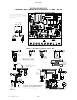
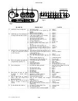
See fig.4 to perform the electrical wiring of the diverter valve to
the main printed circuit board.
LIMITER
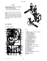
The boiler is equipped with a variable flow limiter at the cold
water inlet. The flow limiter can be adjusted by turning the
screw (see fig.2 pos.
C
) in order to obtain the correct flow rate
of domestic hot water for the specific boiler output.
FLOWSWITCH
This device gives precedence to domestic hot water and is
fitted to boilers which supply instantaneous hot water. It allows
conversion to hot water even with a minimum hot water
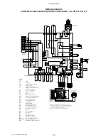
demand (min. 2 litres), using an electromagnetic (see fig. 5)
principle with electrical switching by means of a relay. The
device is made of non-toxic, corrosion-proof ZYTEL 101 L
plastic material which has type approval with non-toxic
characteristics and is unaffected by hard water. In addition, a filter is fitted before the flowswitch and at the cold water inlet
which eliminates any water impurities. These features guarantee that the flowswitch operation is highly efficient.
VALVE
D.H.W. EXCHANGER
D.H.W. EXCHANGER
FLOWSWITCH
Fig. 1
Fig. 4
Fig. 3
Fig. 2
Fig. 1
Fig. 5
Summary of Contents for RSF 24 E
Page 2: ......

