


REGULATION INSTRUCTIONS
RK 100 - RAD - ING - MAN.INST - 1311.1 - DIGITECH CS MIAH4
42
PARAMETER
P03
–
SETS
THE
CENTRAL
HEATING
TEMPERATURE
To enter the parameters menu, follow the previously described procedure
(
see paragraph
5.2 ‘Accessing the parameters menu’
- steps 1-4)
.
5.
Use ‘
’ and ‘
’ buttons
S
symbol side
to modify the value of the
parameter
:
00 = standard (30-80°C)
01
=
reduced (25-45°C) for under-floor heating
6.
Press mode selection button ‘
’ to confirm and to render the new
parameter operative
.
7.
To exit from the parameters menu, press simultaneously ‘
’ and ‘
’
buttons
.
PARAMETER
P04
–
HEATING
OUTPUT
RISING
TIME
This parameter is used to set the time the boiler takes to reach the
maximum power set, during the starting up.
To enter the parameters menu, follow the previously described procedure
(
see paragraph
5.2 ‘Accessing the parameters menu’
- steps 1-4)
.
5.
Use ‘
’ and ‘
’ buttons
S
symbol side
to modify the value of the
parameter
:
00 = 0 seconds (disabled)
01 = 50 seconds (default)
02 = 100 seconds
03 = 200 seconds
04 = 400 seconds
6.
Press mode selection button ‘
’ to confirm and to render the new
parameter operative
.
7.
To exit from the parameters menu, press simultaneously ‘
’ and ‘
’
buttons
.
PARAMETER
P05
–
WATER
HAMMER
PREVENTION
FUNCTION
Activating this function, the D.H.W contact is delayed for 2 seconds
.
To enter the parameters menu, follow the previously described procedure
(
see paragraph
5.2 ‘Accessing the parameters menu’
- steps 1-4)
.
5.
Use ‘
’ and ‘
’ buttons
S
symbol side
to modify the value of the
parameter
:
00 = Off
01 = On
6.
Press mode selection button ‘
’ to confirm and to render the new
parameter operative
.
7.
To exit from the parameters menu, press simultaneously ‘
’ and ‘
’
buttons
.
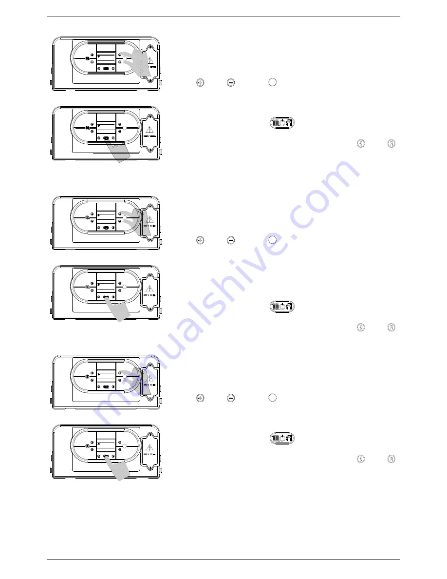
P05
01
P05
00
P04
02
P04
01
00
P03
01
P03
S
S
S
S
S
S