background image

Programming and Operation Using the Dash Buttons 


19  

Min – Max Recall Mode 

The min – max recall mode displays the minimum and maximum reading on all channels since the dash 

was turned on or the min – max values have been manually cleared.  The dash does not need to be in 

Record mode for the min-max values to update.  To display the minimum values enter a SHORT press on 

the 

 button.  The word 

MIN

 will be displayed under the swept tach.  To display the maximum values 

enter a SHORT press again on the 

 button.  The word 

MAX

 will be displayed under the swept tach.  

While you are in min – max mode you may change displays or enter in to scroll mode to see additional 

channels if needed.  To return to Real-time mode and exit min – max mode, again enter a SHORT press on 

the 

 button.  The work 

PLAY

 will appear.  This puts you in Playback mode which we will discuss in 

the next section.  Again enter a SHORT press on the 

 button to return to Real-time mode.  

To clear the minimum and maximum values enter a LONG press on the 

 button in any mode except 

Setup mode. 


Record  Mode 

The Ultra Dash has up to10 minutes of record time.  While in record mode all channels except the warning 

indicators will be recorded.   After a recording you may playback the data on the dash or download it to our 

optional DataLink PC software.  Recorded data will remain in memory, even if the dash is turned off,  for 

up to 2 days or until a new recording has been made.  To enter Record Mode, press and hold the remote 

switch button until the word 

REC

 is displayed below the swept tach position.  To exit Record, mode enter 

three consecutive SHORT button presses on the 

 button.


Playback Mode 

Playback mode allows you to playback recorded data on the dash.  To enter Playback mode, enter a 

SHORT press on the 

 button while in Real-time mode.  This will put you in Min mode. Enter a second 

SHORT press on the 

 button to enter Max mode.  Enter a third SHORT press on the 

 button to 

enter Playback mode.  The word 

PLAY

 will display under the swept tach to indicate you are in Playback 

mode.  Once in Playback mode use the 

 and 

 buttons to move forward and backward in time 

according to the table below.  


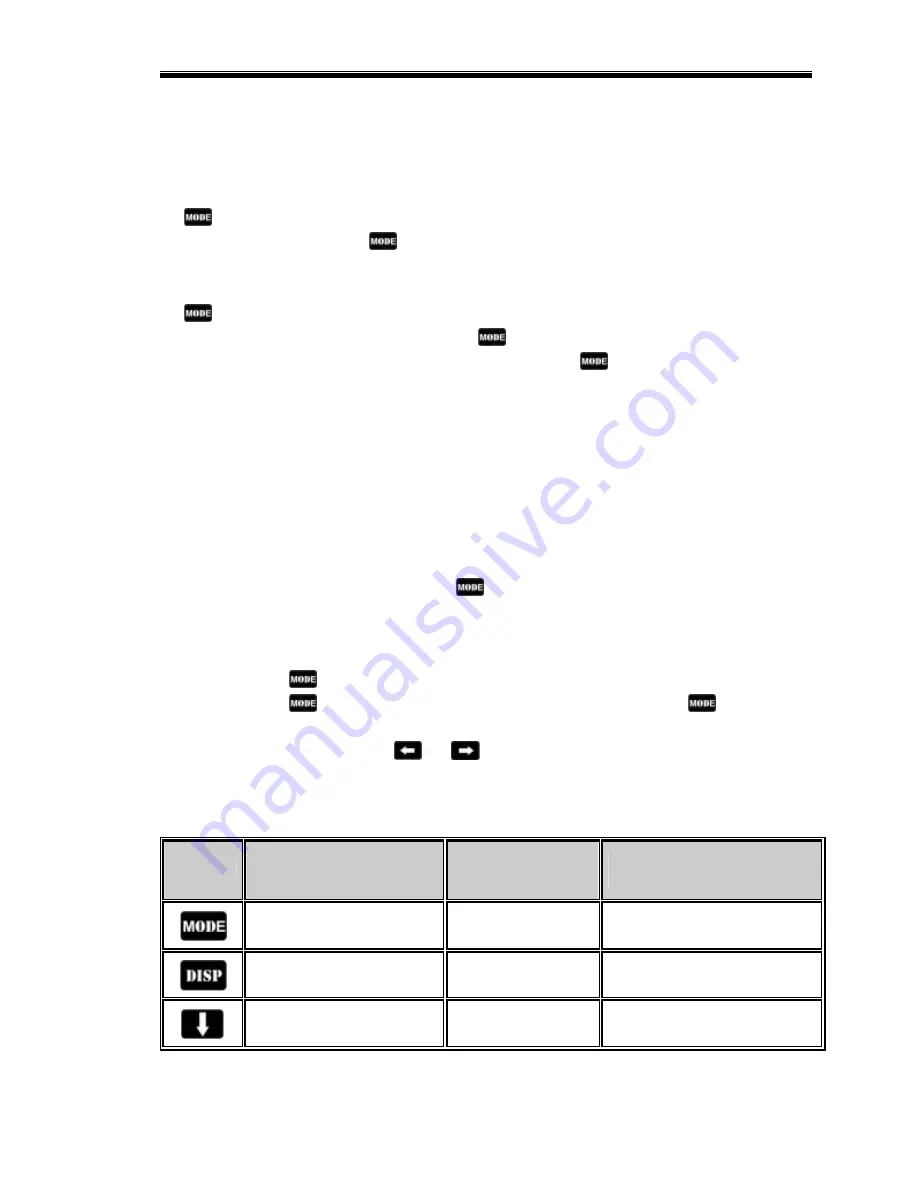
Table 8 shows the behavior of each button while in Playback mode. 

Button 

SHORT Button Press 

(one light flash) 

MED Button Press 
(two light flashes) 

LONG Button Press 

(three light flashes) 


Exit Playback Mode 

Enter setup mode 

Reset minimum & maximum 

recall values 


Change display pages 

Does nothing 

Turn the back light on or off 


Enter scroll mode 

Does nothing 

Does nothing 

Summary of Contents for Ultra Dash Xtreme

Page 1: ...Racepak Ultra Dash Installation and Operation Instructions 300 DS UDX6S...

Page 2: ......

Page 3: ...g Wires from the Connector and or changing EGT Probes 7 Jack Shaft Sensor and Collar Installation 7 Remote Switch 8 External Battery 8 Installing V Net Channels 9 Programming and Operation Using the D...

Page 4: ...r System 28 Configuring Record Parameters 29 Setting the Record Length 30 Setting the Record Enable Channel 30 Setting the Record Start Threshold 30 Sending the Record Parameters 31 Transferring Data...

Page 5: ...dicator output Internal warning indicator light Internal high beam indicator light V Net port for expansion of up to 5 additional channels Ten minutes of record and playback memory Minimum and Maximum...

Page 6: ...Introduction 2...

Page 7: ...e thread lock or nylock nuts on the mounting studs Port Descriptions Connector Locations Port B Serial Port V Net Port Port A Port A Port A is used to connect the main power source warning indicator i...

Page 8: ...er gauge output wire Pin 3 Not Used Pin 4 Premium Fuel Indicator Input Grounding the brown wire will cause the premium fuel indicator to activate Insert the brown wire in pin position 4 Connect the ot...

Page 9: ...e switch in pin position 11 Alternately you can connect the black wire from the remote switch to a good chassis ground instead of running the wire back to pin 11 on the dash Pin 12 Jack shaft RPM and...

Page 10: ...EGT 1 probe in pin position 3 Pin 4 External Battery Ground Connect this wire only if you plan to use an external DC battery to power the dash when the engine is not running Insert the black wire in...

Page 11: ...e required if your current temperature switch uses a larger thread Make sure to use thread sealer when installing the sensor to prevent water leaks Removing Wires from the Connector and or changing EG...

Page 12: ...external Ni Cad battery can be used to power the dash when the engine is not running and power is not available to the main power input at port A pin 13 When the engine is shut off or the main power...

Page 13: ...the V Net extension cable in the V Net port Step 3 Plug the other end of the V Net cable in to the first V Net module You can install up to five V Net modules You can plug the V Net modules in any or...

Page 14: ......

Page 15: ...ctions depending on how long the button is held down In this manual we will refer to the three different button press types as SHORT MED and LONG To help determine when to release the button and as a...

Page 16: ...se or decrease the parameter value in small increments A LONG press on the and buttons will increase or decrease the parameter value in large increments To exit setup mode enter a LONG press on the bu...

Page 17: ...most snowmobiles 6 6 Swept tach engine rpm scale SCAL 0 11 500 rpm max 1 13 500 rpm max 0 7 Engine RPM rev warning REVL 0 20 000 RPM 8 500 8 Jack shaft sensor type R2TY 0 Magnet switch 1 Zero crossing...

Page 18: ...dicator input value when ON PFON 0 input is grounded when ON 1 input has voltage when ON 0 20 Low oil level indicator input value when ON OLON 0 input is grounded when ON 1 input has voltage when ON 1...

Page 19: ...evel Calibration From the factory the fuel level will read from 0 to 5000 If you would like the fuel level to read from 0 to 100 percent you must properly perform the following calibration procedure 1...

Page 20: ...eedometer Upper Left Fuel Level Lower Left Water Temperature Lower Center Maximum Exhaust Gas Temperature Value and Cylinder Number DISPLAY 1 Lower Right Odometer Trip EGT 3 EGT 4 see note below Swept...

Page 21: ...pm and engine jack shaft ratio are not Also if you have added any channels on the V Net port you can use scroll mode to view them The only way to view these channels is to enter scroll mode To enter s...

Page 22: ...OT Water temperature VOLT External battery volts when running on external battery power Rectified volts when running on main AC DC power RAT Engine to jack shaft ratio Engine RPM divided by Jack Shaft...

Page 23: ...arning indicators will be recorded After a recording you may playback the data on the dash or download it to our optional DataLink PC software Recorded data will remain in memory even if the dash is t...

Page 24: ...lay in the lower left position on the LCD External warning light output see Wiring Port B All of the warning inputs do not activate all three warning indicator types Some only activate the alpha displ...

Page 25: ...g a MED press on the button This will clear the warning only for that occurrence If the input that activated the warning falls below the warning limit and is later activated again the alpha warning wi...

Page 26: ......

Page 27: ...f you have purchased the PC download package you will need to insert the disk and click on the OK button If you have purchased the PC programming software then just click on the Demo Only button If yo...

Page 28: ...ep is to connect your PC to your dash using the serial interface cable supplied with the DataLink software The next step is to start the DataLink program by clicking on the DataLink icon located on th...

Page 29: ...channel After you have opened the car configuration file the next step in modifying the setup of your system is to select the device channel to be modified To select a device channel position the mous...

Page 30: ...of sensor connected to the channel The following describes the basic sections of the edit dialog box and their locations Online Help Box The online help box is a scrollable text area containing detai...

Page 31: ...age Device Programmed Successfully at the bottom of the massage log Select the OK button to exit the dialog box As a final step save the car configuration file to your disk by clicking on the save ico...

Page 32: ...dash using the serial communication cable and power up your system Next select the ReadVNet Config selection located in the Editmain menu selection The DataLink software will now query the V Net modu...

Page 33: ...o begin recording only after one of the monitored data channels exceeds a preset threshold For instance the logger can be programmed to begin recording any time the Engine RPM exceeds 3000 rpm Once th...

Page 34: ...number of seconds to record Enter the new desired value in the edit box Setting the Record Enable Channel To program the record enable channel locate the Can ID for Record Enable channeloption and se...

Page 35: ...he Record Parameters The final step in programming the record parameters on your dash is to send the configuration you just edited to from your PC to your dash over the serial communication cable To s...

Page 36: ......

Page 37: ...d you will be asked to select which configuration file to use Select the configuration file that contain VDash and your serial number as discussed the previous section The system will transfer the dat...

Page 38: ...the Run Log sections that are user programmable to allow test information to be entered during the download process Fill out the information as appropriate The file save dialog box will then be displa...

Page 39: ...Remember that only channels in the right hand list will be displayed during a real time telemetry session Next select the Real Time Sample Rate from the options list in the lower left hand corner of...

Page 40: ...ct the Telemetry icon shown below or the New Telem Session menu item located in the File main menu selection A dialog box as shown below will be displayed and you will then be asked to select the conf...

Page 41: ...u All previously recorded data will be erased from the file If you wish to save the data stop the data acquisition and use click the Save icon located in the tool bar or select Save located in the Fil...

Reviews: