FDV451 / MQFDV453 Vertical Vent Installation
A firestop must be installed on the bottom side of the joists when passing through a ceiling or floor. If an attic insulation shield is to be
used, a firestop is not required.
One pair (two) 45° elbows may be used to provide an offset in order to avoid cutting of joists and to clear other obstructions.
When using 45° elbows, an elbow support is required directly above the highest elbow.
When installing a bend in a joist area a minimum of 2” clearance to combustible to the top of bend must be maintained, sides and
bottom of pipe, a 1” clearance to combustibles must be maintained. If running horizontally through an area, a 1” clearance to the top of
the horizontal pipe must be maintained.
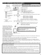
Maximum vertical height of system should not exceed 45 feet.
Spacer springs to be installed on 4" flex pipe every 3 ft. on vertical runs. On 45° elbows or 90° elbows a spacer spring is needed on the
start of the bend and on the end of bend.
NOTE: You may be required to connect 2 lengths of flex pipe
together to achieve the desired length.
The parts are listed below:
ZDV4FC Flex Connector 4” diameter (needed to join 4” flex
together) and (4) screws.
FDVVSK: Vertical Vent Starter Kit
Starter Kit contains: Attic Insulation Shield, Decorative Ceiling Trim Ring,
Black Band, brass Band, Roof Support, Spacer Springs (6), Mill Pac.
FDVVT40 Termination
ZDV7SC Storm Collar
ZDVRS Roof Support
ZDVAAF (Flashing 1/12 to 7/12) c/w Storm Collar
ZDVAF2 (Flashing 8/12 to 12/12) c/w Storm Collar
ZDVAF3 (Flashing Flat) c/w Storm Collar
ZDV48GP Pipe Galvanized (Always needed, used in
roof support and to support pipe / termination)
ZDVAIS Attic Insulation Shield (required when passing through attic space)
FDV48P (7” Diameter x 48”) Black Pipe
FDV36P (7” Diameter x 36”) Black Pipe
FDV24P (7” Diameter x 24”) Black Pipe
FDV12P (7” Diameter x 12”) Black Pipe
ZDV4FP8 Flex Pipe 4” Diameter (4’ unexpanded to 8’ expanded)
ZDV4FP20 Flex Pipe 4” Diameter (10’ unexpanded to 20’ expanded)
ZDVFS Firestop Spacer (required when passing through floors and ceilings)
ZDVVOS Offset Support Strapping (needed to support pipe when bending)
FDVE45 (7” diameter x 45°) Black Elbow
FDVE90 (7” diameter x 90°) Black Elbow
ZDV4SS Spring 4” Standoff Spacer (Used for spacing off 4” flex from 7” black pipe)
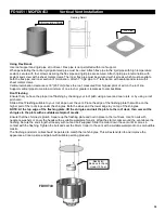
This would be a 3/12 Pitch
12” Rule
Level
Roof
3”
Adjustable Clamp
2 self-tapping screws
3 self-tapping screws to
secure rigid pipe and
termination
Rigid Pipe
Roof Support
Vertical Venting in Cold Climates
In cold climate conditions where temperatures go below -10°C [14°F], we recommend that the chase be insulated and where the vent pipe
enters into the attic space that the pipe be wrapped with an insulated Mylar sleeve. This will increase the temperature of the vent and help the
appliance to vent properly in cold weather conditions.
It is also important in vertical vented direct vent appliances that the appliance be operated daily during the winter months as this will help stop
the Termination from freezing up. We recommend using a thermostat set at room temperature to allow the unit to cycle.
For IPI models it may be necessary to set the appliance to Standing Pilot mode to maintain heat in the cavity. The purpose of this procedure is
to prevent cold air from penetrating the chimney and then onto the living space. Therefore, when the internal temperature is slightly elevated
the fireplace is able to freely exhaust its combustion and hence making it easier to startup.
An Attic Insulation Shield must be
installed where the vent passes from
a lower living space into an attic
space where the chimney is not
enclosed. It is designed to keep
insulation materials away from the
chimney.
When installing the Attic Insulation
Shield where the chimney passes
from a living space to an attic space,
install
the shield from below and
nail in place using 1" spiral nails.
18” Min
Clearance above highest point
of exit on roof 18 inches (45cm).
Clearance to perpendicular wall 24 inches
(60 cm). (Recommended to prevent re-
circulation of exhaust products. For additional
requirements check local codes.)
24” Min
65
Summary of Contents for Kingsman FDV451LP
Page 42: ...Gas Conversion for Modulator PART C 42...
Page 47: ...Configuration 1 Basic manual HI LO and manual ON OFF capabilities 47...
Page 48: ...Receiver Module 584 523 521 221 1001 P221SI Receiver Module 584 523 521 221 1001 P221SI 48...
Page 55: ...Proflame 2 Remote Control 55...
Page 57: ...57...


