


COMMON PARTS
Valve System Parts / Millivolt
1000-P136WR
Generator / Thermopile
1001-P069SI
Electrode Sparker 915.069 TC SIT
1001-P216SI
Thermocouple 290.216 TC SIT
1001-P165SI
Orifice Pilot NG 977.165 TC SIT
1001-P167SI
Orifice Pilot LP 977.167 TC SIT
1001-P280SI
Tubing 24”
1001-P633SI
Valve Nova LP Hi/Lo 0820651
1001-P634SI
Valve Nova NG Hi/Lo 0820652
1001-P713SI
Pilot Burner LP 199.713 TC SIT
1001-P714SI
Pilot Burner NG 199.714 TC SIT
Electronic Ignition Replacement Parts IPI
1006-P002si
Valve IPI (NG; Hi/Lo)
1006-P003si
Valve IPI (LP; Hi/Lo)
1002-P047si
Pilot Assembly (LP)
1002-P033si
Pilot Assembly (NG)
1002-P017si
Spark Electrode (24”)
1002-P903si
Electrode Flame Sensor (24”)
1002-P302si
IPI Ignition Board
1002-P850si
AC Wall Adapter
1002-P12BH
Battery Pack
1002-P912si
Wiring Harness
1001-P166si
Orifice Pilot (NG)
1001-P168si
Orifice Pilot (LP)
1002-P013si
Stepper Motor (NG)
1002-P012si
Stepper Motor (LP)
1002-P016si
Hi/Lo Regulator (NG)
1002-P014si
Hi/Lo Regulator (LP)
6961-P161
16” Extension Cord
Conversion Kit
450DV-CKLP
Conversion Kit - Millivolt - To Propane
450DV-CKNG
Conversion Kit - Millivolt - To Natural
Gas
450DV-CKLPI
Conversion Kit - IPI - To Propane
450DV-CKNGI
Conversion Kit - IPI - To Natural Gas
Miscellaneous Parts
1000-150GE
Silicone GE Red IS806 #736
1000-150MP
Hi-Temp Millpac Sealant 840099
1000-214
Piezo-Igniter 1244-17 MARK 21
1000-215
Pal Nut (18MMXI.5MM)BLK (1364.03)
1000-218
Switch Ivory (1451/001)
1000-227
Cover Ivory (86001/001)
1000-255
Orifice Brass - (State Size)
3600-B139
Explosion felt Gasket
2000-080
Thermodisc 2450 (For Blower)
1000-306
Thermalcord - Adhesive Back for Door
Frame
1000-085
Control Variable Speed KBWC-13BV
FP15GC
Stainless Steel Gas Connector
450FDV-300
Front Glass
453FDV-309
Side Glass
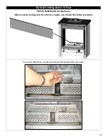
KINGSMAN FIREPLACE VENTING
FDVHSK
Horizontal Vent Starter Kit - (Direct Vent
Stoves)
Starter Kit Contains:
Horizontal Vent Termination, Zero Clearance
Wall Sleeve, Black Wall Trim Ring, 7" Dia.
Black Pipe 24" Length, 7" Dia. Black Pipe
48"Length 7" - 90 Degree Black Elbow, 4" Flex
48" Unexpanded (96" Expanded)
7" Black
Bands(3), Mill Pac.
FDVVSK
Vertical Vent Starter Kit - (Direct Vent
Stoves)
Starter Kit Contains:
Attic Insulation Shield, Fire Stop, Ceiling Trim
Plate,
Black Trim Ring (2), Roof Support,
Spacer Springs(6), Mill Pac
Z47VT
Vertical Vent Termination
FDVVT40
Vertical Vent Termination Converts from 15’ -
40’ to 15’ and under
FDVHT
Horizontal Vent Termination
FDVHSCU Safety Cage for Horizontal Termination
FDVHSQ
Horizontal Square Termination
Z47ST24
Horizontal Snorkel Termination
(24” Tall, 14-1/2” Center to Center)
Z47ST36
Horizontal Snorkel Termination
(36” Tall, 26-1/2” Center to Center)
Z57STSC
Safety Cage for Horizontal Snorkel
Termination
FDV48P
Black Pipe (7" Diameter x 48")
FDV36P
Black Pipe (7" Diameter x 36")
FDV24P
Black Pipe (7" Diameter x 24")
FDV12P
Black Pipe (7" Diameter x 12")
FDVE90
Black Elbow (7" Diameter x 90 Degree)
FDVE45
Black Elbow (7" Diameter x 45 Degree)
ZDVDKA
Dura-Vent Stove Adapter ( for Direct Vent
Stoves)
ZDVAIS
Attic Insulation Shield
ZDVVOS
Offset Support
ZDVFS
Firestop Spacer
ZDVRS
Roof Support
ZDVSS
Siding Shield
ZDVWT
Wall Thimble (Horizontal Venting)
ZDV48GP
Galvanized Pipe 7" Dia. x 48" (Vertical
Installations)
ZDV4FP8
Flex Pipe 4" Diameter (4' Unexpanded to 8'
Expanded)
ZDV4FP20 Flex Pipe 4" Diameter (10' Unexpanded to 20'
Expanded)
ZDV4FC
Flex Connector 4" Diameter
ZDV4SS
Spring 4" Standoff Spacer
ZDVAAF
Flashing 7" c/w Storm Collar (1/12 to7/12)
ZDVAF2
Flashing 7" c/w Storm Collar (8/12 to 12/12)
ZDVAF3
Flashing 7" c/w Storm Collar Flat
ZDV7SC
Storm Collar 7 Inch
71
Summary of Contents for Kingsman FDV451LP
Page 42: ...Gas Conversion for Modulator PART C 42...
Page 47: ...Configuration 1 Basic manual HI LO and manual ON OFF capabilities 47...
Page 48: ...Receiver Module 584 523 521 221 1001 P221SI Receiver Module 584 523 521 221 1001 P221SI 48...
Page 55: ...Proflame 2 Remote Control 55...
Page 57: ...57...


