FDV451 / MQFDV453 Venting Routes and Components
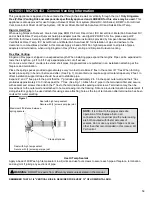
Since it is very important that the vent system maintain its balance between the combustion air intake and the flue gas
exhaust, certain limitations as to vent configurations apply and must be adhered to.
See venting chart for total horizontal and vertical runs
For every 90° elbow after the first 90° elbow the horizontal run must be reduced by 36”.
For every 45° elbow after the first 90° elbow the horizontal run must be reduced by 18”.
This does not apply if the 45° elbows are installed on the vertical part of the vent system. 45° elbows can be installed in
either the horizontal or vertical runs.
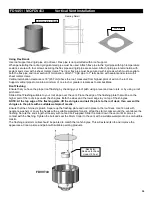
Minimum clearances on venting (2" to top of elbow), (1" from top of horizontal pipes), (1" on all other existing pipes).
Only trim kit(s) supplied by the manufacturer shall be used in the installation of this appliance. Draft Relief Openings must
not be covered or blocked.
IMPORTANT: Always locate the fireplace in such a way that a minimum of offsets and/or horizontal runs are required.
1/4” vertical rise is required for every 12” horizontal run.
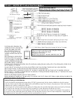
The minimum allowable configuration is
4-1/2 feet vertical with unit 2-1/2” from
wall.
4-1/2
Feet
2
Feet
2-1/2”
20
Feet
7
Feet
45 Feet
Max
The maximum horizontal vent run with one 90°
elbow attached is 20 feet with 7 feet vertical.
The maximum vertical rise is 45 feet.
Support Straps
every 3 Feet
60
Summary of Contents for Kingsman FDV451LP
Page 42: ...Gas Conversion for Modulator PART C 42...
Page 47: ...Configuration 1 Basic manual HI LO and manual ON OFF capabilities 47...
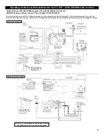
Page 48: ...Receiver Module 584 523 521 221 1001 P221SI Receiver Module 584 523 521 221 1001 P221SI 48...
Page 55: ...Proflame 2 Remote Control 55...
Page 57: ...57...


