Q150T Sample Preparation System
Q150T - Instruction Manual
71
10473 - Issue 5
7.14
Emergency Stop Module
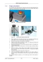
The emergency stop module (Part No. 11223) sits on top of the right hand side of the
instrument. In the assembly there is the main stop box, the power plug and cable and the
safety bracket to stop removal of the power plug.
Figure 7-18.
The emergency stop module
Figure 7-19.
Connecting the emergency stop module
1.
Before starting work on the instrument ensure it is not operating, turn off the main
power switch on the rear of the instrument and unplug the power lead.
2.
Remove the two screws on the top left or the rear panel.
3.
Position the main stop box as shown in Figure 7-18, making sure the plug and
cable do not scratch the instrument case.
4.
Secure the main stop box to the rear panel using the two M4 x 10 recessed pan
headed screws provided.
5.
Connect the power plug from the stop box in to the main power switch (see Figure
7-19).
6.
Remove the screws in the two holes to the immediate right of the main power
switch and fit the safety cable bracket using the M4 x 6 recessed pan headed
screws provided.
7.
Plug the main power lead into the socket in the stop box.
8.
Check the red knobbed emergency stop switch is in the working position by
removing the key and striking the red knob then turning the key to the right to
release.
The instrument should now power up in the normal way when the main switch is
operated.
Summary of Contents for Q150T S
Page 92: ......


