3
rd
Generation Dual Channel
Compact RDMS
TM
Telemetry Receiver-Combiner
70
Quasonix, Inc.
specified since it can be applied to either a C or P band signal. The downconverting antenna setting
determines how a specified C band frequency is interpreted in a system where both C and P bands are
enabled.
If a C band frequency is specified and the downconverting antenna is
enabled
, it is assumed the signal is a
C to P downconverted signal. The receiver is tuned to the P band equivalent and the automatic inversion is
used. If the downconverting antenna is
disabled
, the receiver is tuned to the specified C band frequency and
spectral inversion is not an issue.
If a P band frequency is specified, it is assumed there is no downconverting antenna. The receiver is tuned
to the actual P band frequency and the automatic spectral inversion is disabled.
5.4.14 Clock/Data Output Controls
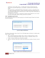
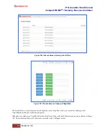
The Clock/Data Output Controls section contains parameters for clock and data output for Channel A and Channel
B, as shown in Figure 94.
Figure 94: Output Controls Window
The Channel A Output options, shown in Figure 95, select what signals appear on the Channel A clock/data outputs:
DQE, No DQE, or Test Data.
•
DQE – Selecting DQE enables encapsulation of data on Channel A; if DQ Encapsulation is enabled
(checked) on the Configuration Basic Settings window, the output is encapsulated, otherwise it is not
•
No DQE – Selecting No DQE bypasses data quality encapsulation
•
Test Data – Selecting Test Data causes the output of the Data Generator to display on Channel A clock and
data
Figure 95: Output Controls, Clock/Data Output Channel A

