3
rd
Generation Dual Channel
Compact RDMS
TM
Telemetry Receiver-Combiner
67
Quasonix, Inc.
5.4.13.5 AGC Time Constant
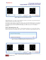
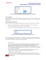
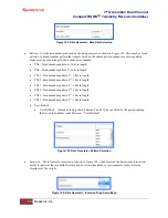
The Time Constant option, shown in Figure 89, sets the time constant of the AM/AGC front panel MDM-25 output.
The time constant can be set in units of ms (milliseconds). The higher the time constant, the slower the AGC output
voltage will move in response to changes in input signal level.
Because the AM/AGC front panel MDM-25 output tracks any input signal level changes that are not tracked by the
AGC, the AM output will include any signal amplitude frequency content from (approximately) the inverse of the
AGC time constant up to the AM bandwidth limit. For example, if the AGC time constant is set to 100 ms and the
AM bandwidth is set to 100 Hz, then the AM output will include any AM frequencies between roughly 10 Hz and
100 Hz.
To change the AGC Time Constant, type the new value, in ms, or use the up/down arrows to scroll to the desired
value.
Figure 89: Antenna Controls Window, AGC Time Constant Selection
5.4.13.6 AGC Freeze
The AGC Freeze option disables the hardware gain compensation loop such that gain from the RF input to the IF
output is fixed. The receiver front end becomes a constant gain block, which may be useful for making receiver
noise figure measurements or antenna G/T measurements. Note, however, that RSSI measurement and AM/AGC
outputs will continue to reflect changing input levels within a +/-16 dB window around the frozen level. Also, RSSI
is calibrated to be precise enough—even varying front-end gain—that AGC Freeze is not absolutely necessary to
obtain excellent noise figure or G/T readings via the RSSI measurement.
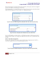
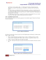
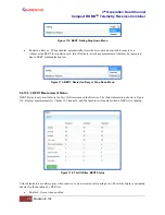
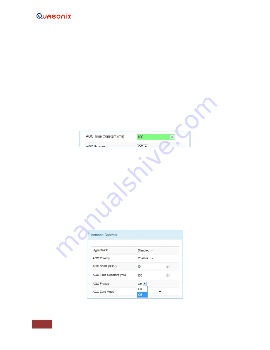
Click on the drop down menu to select On or Off, as shown in Figure 90.
Figure 90: Antenna Controls Window, AGC Freeze Selection


