3
rd
Generation Dual Channel
Compact RDMS
TM
Telemetry Receiver-Combiner
43
Quasonix, Inc.
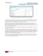
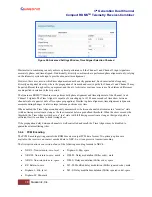
Figure 49: Advanced Settings Window
5.4.3.1
Measured Bit Rate Setting
Measured Bit Rate displays the receiver’s bit rate on the input signal. This value may be copied and set as the
specified bit rate. The purpose of this process is to eliminate unintended bit rate offset error so that the receiver can
make full use of its bit synchronizer tracking range, or optionally reduce its tracking range. For the receiver to have
an accurate measurement, however, the input signal must be close enough to the previously commanded bit rate to
be within the current bit synchronizer lock range and actually be locked.
5.4.3.2
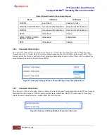
IF Filter
Based on the receiver’s high level of integration, the proper IF filter is automatically selected based on the current
mode and bit rate settings of the demodulator. Although manual filter selection is available through the IF Filter
Menu, manual selection is not recommended. In the case of a receiver with diversity combining enabled, the two
channels must have the same IF filter selected for proper operation.
The basic premise of trellis demodulation relies on the precise phase modulation of the transmitted signal. Some
older analog transmitters have an inordinate amount of phase noise, reducing the effectiveness of the trellis
demodulator. In Tier 0 (PCM/FM), enabling the Phase Noise Compensation option relaxes the requirements of the
trellis demodulator, allowing better receive performance for transmitters with a high degree of phase noise.
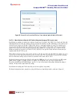
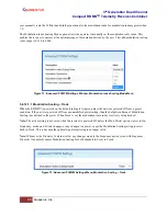
When the modulation is set to PCM/FM, the Filter Settings window includes settings for IF and Phase Noise
Compensation. In any other mode, only the IF Filter option is available.


