


Page
30
AN-X-TI-MAS
November 2011
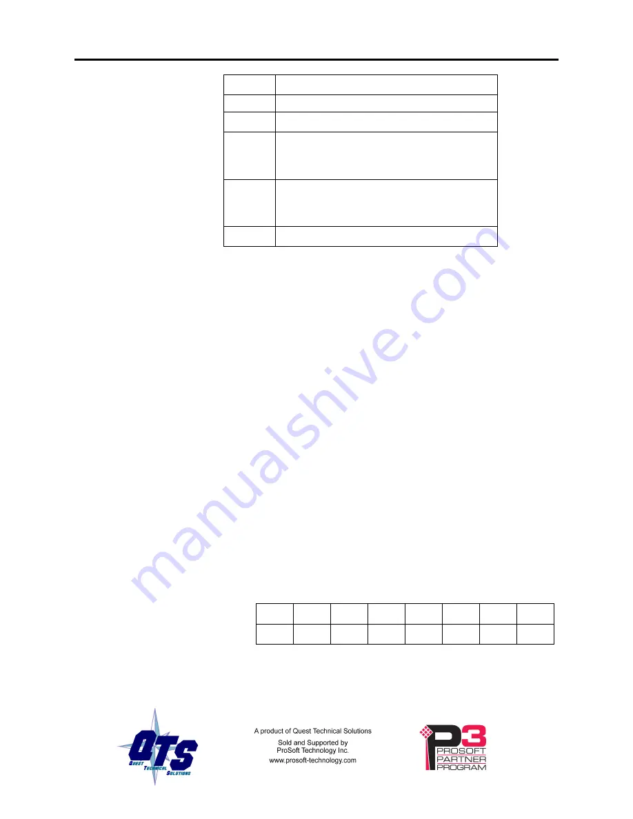
Offset
Counter Description
network was reinitialized.
12
Last I/O scan time * 100 us
13
Minimum I/O scan time * 100 us. Max and
Min are updated then recalculated every
6.5536 seconds.
14
Maximum I/O scan time * 100 us. Max and
Min are updated then recalculated every
6.5536 seconds.
15
Reserved
Base Module Fault Table
The base module fault table contains the status of the module in each
slot. This table is updated on each scan.
There is one word per base. The status of base 1 is found at offset 21, the
status of base 2 is found at offset 22, and so on. Bit 0 corresponds to slot
1, and so on.
The bit is 0 if there is no module fault and is 1 otherwise. The bit is 1 for
unoccupied or unconfigured slots.
Base Status Table
The base status table contains the status returned by each base. This table
is updated on each scan. The data in the base status table is returned by
the base and is valid only if the base is not in error.
TIP
The base status table is used internally by the AN-X-TI-MAS and should
not be used by a ControlLogix application. The values are provided here
for reference only.
There is one word per base. The status of base 1 is found at offset 41, the
status of base 2 is found at offset 42, and so on.
There are 8 status bits for each base. More than one bit can be set in the
status for a base. The bits are assigned as follows:
7
6
5
4
3
2
1
0
MUF
TE
TCP
LR
DB
MM
MF
MTO
Bit 0, module transitioned online (MTO), is set to 1 whenever a
mismatched module has been replaced. It is cleared to 0 when the
scanner reads the status of the modules in the base.


