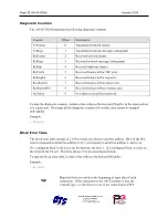
AN-X3-GENI Page
25
;,m31>5[2],b05_OutMon, ; Ofs= 7 Len= 2 IC660BBA020 24/48VDC 4In/2Out Analog Block
;,m31>10[12],b10_OutMon, ; Ofs= 9 Len=12 IC670GBI001 Field Control Genius Bus Interface Unit
;,m31>11[2],b11_OutMon, ; Ofs= 21 Len= 2 IC200GBI001 VersaMax Genius Network Interface Unit
;The following lines map Diagnostics into ClxSlot 15
ClxSlot,15
DataInput ; Inputs to ControlLogix
0,BlockFlt, ; Ofs= 0 Len=2
2,ConnDiag, ; Ofs= 2 Len=8
10,DiagCtrs, ; Ofs= 10 Len=10
;ControlLogix Connection Statistics
,ConnStats0, ; Ofs= 20 Len=10
Viewing and Retrieving the Current Configuration
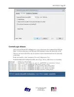
To view the Genius configuration currently in AN-X, access the web interface and select
Automation Network/ Configuration View
.
Links are provided to retrieve the I/O and Ethernet/IP configuration text files.
Links are also provide to retreive ControlLogix aliases. Select
Logix Aliases
, either
Owner
or
ListenOnly
.
Genius Configuration File Format
The Genius I/O configuration file defines the contents of the Genius network to be scanned.
It is a text file, which can be created and edited with a text editor such as Windows Notepad.
Anything after a semicolon on a line is treated as a comment. Comments can be inserted at the
end of a line or on a separate line.
Genius Block Definitions
Each Genius block on the network is defined by a line in the configuration file. The line contains
various parameters that describe the block.
Parameters are identified by keywords and are separated by spaces or commas.
Each definition begins with the parameter that defines the serial bus address of the block being
configured, for example, Block=7. The serial bus address can be from 0 to 31.
The input length is defined by the keyword Inp= and can range from 0 to 128 bytes. If the input
length definition is omitted, the input length defaults to a length of 0.


