background image

22

23

CHAPTER 5  BASIC OPERA

TION

When you launch the SuperDVR program, it will open to the 

Main Display Interface

 which 

will show the video feeds from the cameras as well as the 

Display Control Panel

BASIC OPERATION

CHAPTER 5

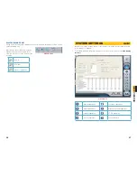
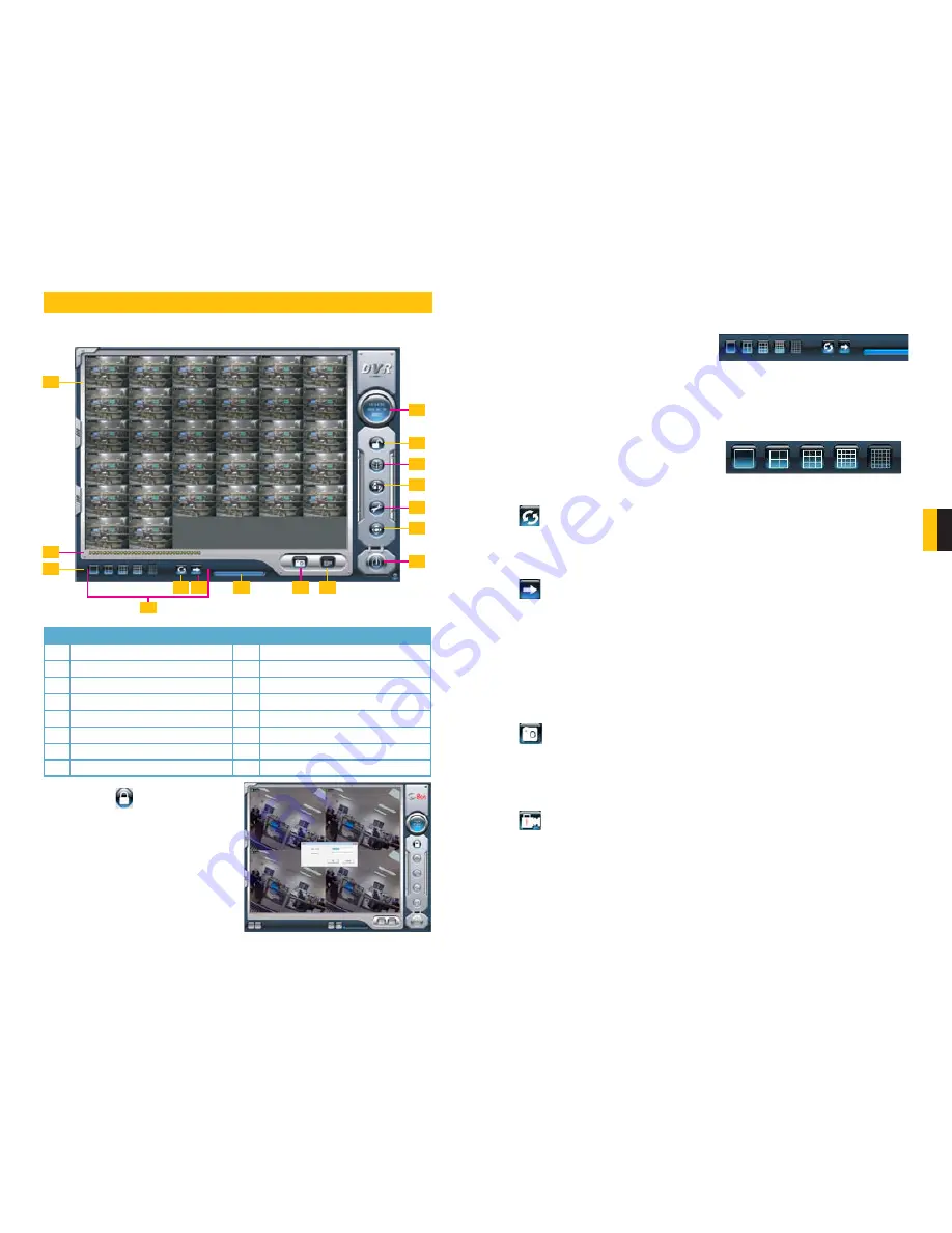
5.2 DISPLAY CONTROL PANEL

The Display Control Panel includes the Display Mode buttons along with buttons which allow 
you to cycle automatically or manually through individual or groups of channels. 

1

3

2

4

5 6

7

9

8

10

11
12
13
14

16

15

No. Item

No. Item

1

Display Window

2

Record Status Panel

3

Display Modes

4

Display Control Panel

5

Dwell Time

6

Page Flip

7

Drive Capacity Indicator Bar

8

Snapshot

9

Urgent Record

10

Date and Time

11

Login

12

Emap

13

Search and Playback

14

Configurations

15

PTZ Control

16

Exit

PICTURE 5-1

PICTURE 5-3

PICTURE 5-2

DISPLAY MODES

Choose the number of channels you wish to view simultaneously. If you have fewer cameras 
than portions of the screen, those channels without cameras will remain black.
Available modes are single-, four-, nine-. 16- 
and 36-screen displays. The software will only 
display the modes appropriate to the number 
of cameras you have connected.


AUTO DWELL DISPLAY

If the 

Main Display

 is currently showing fewer channels than are available, you can have the 

DVR automatically cycle through and show the feed from each camera or group of cameras 
by selecting the button. 


PAGE FLIP

This button allows you to manually cycle through the channels. Like the Auto Dwell feature, if 
there are more channels available than are currently being displayed in a multi-screen display 
mode, this button will take you to the next group of video feeds.

5.3 OTHER CONTROLS

Log In

 will be covered in the following section and the remaining operations on the left 

hand side of the 

Main Display Interface

 will be covered in 

Chapter 7.

 The two remaining 

functions are 

Snapshot

 and 

Urgent Record

.

 SNAPSHOT

Usable in single image display mode, pressing this button will take a series of still images 
from the camera currently being displayed and will save them to a location on the hard drive. 
Settings to determine the number of images (up to 32) as well as the location to where they 
will be saved will be covered in 

Chapter 6

.

 URGENT RECORD

Clicking the Urgent Record icon will cause all cameras to begin recording regardless of their 
schedule or recording mode. Video will be saved to the location designated by the user. Like 
Snapshot, the settings for this feature will be covered in 

Chapter 6

.

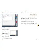
Buttons currently in effect are highlighted. 
The Drive Capacity Indicator Bar will fill in as 
more files are recorded to the drive. When the 
drive is at capacity, the bar will be red.

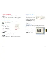
5.1 LOG IN 

Located on the left side of the 

Main Display 

Interface

, clicking on the lock icon will open 

the 

Login

 window. Enter your user name and 

password to access the controls. The default 
user name is 

System

 with no password 

required. You can add a password and create 
other user accounts as described in 

Section 

7.4 User Configuration

.

PICTURE 5-4

Summary of Contents for QSDT4PCRC

Page 1: ...1 4 and 8 Channel H264 Real Time Recording PC Based Network DVR PCI Cards User Manual MODEL QSDT4PCRC QSDT8PCRS...

Page 2: ...certain to make the most of your warranty by completing the registration form online In addition to warranty and technical support benefits you ll receive notifications of product updates along with f...

Page 3: ...4 Record Search and Playback 30 Record Search 31 Playback 32 6 5 Other Functions 33 File Backup 33 Deleting Recorded Files 34 Capture Pictures 34 Digital Image Zoom 36 7 System Settings 37 7 1 Basic C...

Page 4: ...1 Windows Mobile Pro 79 10 2 Symbian 81 10 3 iPhone and iPad 83 Installing through the iPhone or iPad 83 Installing through PC or Macintosh Computer 85 Operating Instructions for iPhone iPad 86 10 4...

Page 5: ...recorded data will be covered by new data Users can also set hard drive minimum storage alarm Then once the present storage space is less than the minimum storage and recycling record mode is not enab...

Page 6: ...imum or later Intel processor Motherboard Intel with Intel system chipset Hard Drive 500GB minimum RAM 1GB minimum Video Card Supports MOST AGP and PCI E Video Cards with 256MB of RAM or more with ful...

Page 7: ...e remote monitor Link the con2 to con1 ports on the cards with the last card linking to the Spot Out port on the face plate PICTURE 3 3 PICTURE 3 4 PICTURE 3 5 AUDIO You will only need to install the...

Page 8: ...ch to the two 15 pin receivers on the card Each dongle supports four channels of video and four channels of audio P4 P3 Video 1 GND Video 2 GND Video 3 GND Video 4 GND GND Audio 1 Audio 2 Audio 3 Audi...

Page 9: ...sh to use external alarm sensors The DVR card has built in motion detection software which can be used to trigger alarms when motion is detected by a camera Pin Port Define Interpret Pin Port Define I...

Page 10: ...in the CD s menu by copying the installer to your hard drive and then double clicking to begin the process STEP 2 Once the Setup window opens click Next to begin the installation STEP 3 Select your vi...

Page 11: ...r account PICTURE 4 7 PICTURE 4 8 PICTURE 4 10 PICTURE 4 9 Windows 7 1 Open up the Start Menu accessible by clicking on the Windows icon in the lower left of your screen 2 Type uac into the search bar...

Page 12: ...y cycle through the channels Like the Auto Dwell feature if there are more channels available than are currently being displayed in a multi screen display mode this button will take you to the next gr...

Page 13: ...ecording quality and frame rate the more space the recorded file s will occupy on the hard drive Time Stamp By selecting this option the record date time message appears in the recorded file images Sw...

Page 14: ...atus indicator light will turn red MOTION DETECTION RECORD MODE This will enable the system to detect image changes and begin to record by activating motion detection and motion alarm recording For in...

Page 15: ...to go with an early morning schedule you will need to repeat the process Clicking on Delete will remove a specific block of time from a specific day s schedule Copy To allows you to apply the setting...

Page 16: ...er right of the display will return you to live surveillance in the Main Display Interface PICTURE 6 10 PICTURE 6 11 PICTURE 6 12 STEP 1 Select whether the program should search in the normal destinat...

Page 17: ...to a certain point in the record by clicking on and sliding the progress indicator At the top of the file visualizer the bar represents the time when the file was recorded Clicking on this will magnif...

Page 18: ...E This feature is only available in Playback Pause mode on a single channel These changes will not affect the actual recorded image Pressing the Default icon in the lower right of the panel will resto...

Page 19: ...recording PICTURE 6 22 Zoom In Zoom Out Revert to original size SYSTEM SETTINGS CHAPTER 7 Beyond the recording settings there are other features of this video capture card which need to be enabled or...

Page 20: ...seconds of a screen here PICTURE 7 2 PICTURE 7 4 PICTURE 7 3 Caption There are four options None ID Name and ID Name for users to select for all the channels None means no title or name ID means camer...

Page 21: ...ontinues after sensor stops Disk Shortage Alarm If the Partition free space is less than the set percent the system will stop recording or recycling but will sound an alert according to the settings A...

Page 22: ...ed the alarm will be sent to the selected mailbox PICTURE 7 10 PICTURE 7 11 PICTURE 7 12 NOTE Only one picture will be attached for each alarm event 7 3 E MAP CONFIGURATION E map is used to show full...

Page 23: ...in another viewing mode PICTURE 7 13 PICTURE 7 14 PICTURE 7 15 USER RIGHTS Select a user in the User Configuration area and click Edit to enter the Edit User area Users can edit user s password and r...

Page 24: ...g the Baud Rate Protocol and Address ready before you begin 8 1 P T Z CONTROL CONFIGURATION The PTZ settings are found in the Configuration menu Click on the wrench icon on the right side of the Displ...

Page 25: ...ht level are adjusted by the use of the and keys to either side A PTZ function direction zoom etc will continue as long as the user is holding down the left mouse button while the cursor is over the b...

Page 26: ...ity setting Microsoft O ce Outlook 2007 Microsoft Internet Explorer All Programs Devices and Printers Default Programs Help and Support iTunes Adobe Acrobat Inbox Microsof iTunes start start Shut Down...

Page 27: ...plication to install it STEP 4 Click on the detect_routers application to run it If Multiple Routers are Detected If there are multiple routers you will see a display similar to Picture 9 8 If so it m...

Page 28: ...list Click on the program to launch it STEP 3 Once Simple Port Forwarding has launched select your router from the list The default Router IP and Login information will automatically come up If you h...

Page 29: ...15 If for some reason a port or ports that you forwarded are not listed in the Router and if you see a message in the Scripts list on the left side of the window stating that the port already exists...

Page 30: ...s that shows the WAN Internet IP address and write it down this WAN IP address STEP 3 Log into the Router 2 by putting the IP of Router 2 into the Internet Explorer browser as in example shown in Pict...

Page 31: ...Settings Your domain name will look like this http example myq see com STEP 4 Once you have obtained your domain name you will need to configure the DVR for access using it 9 4 ACCESSING THE DVR USING...

Page 32: ...in the lower left of your screen STEP 2 Type uac into the search bar and hit ENTER The User Account Control will open or you will be offered a link to click to open it STEP 3 Move slider to lowest se...

Page 33: ...lose Internet Explorer You are now ready to access the DVR using Internet Explorer PICTURE 9 38 Open a browser window in Internet Explorer and enter the IP address or DDNS name obtained in Section 9 3...

Page 34: ...when logging in from the computer itself The default User Name is SYSTEM without a password Once you have entered the User Name and Password click OK to log in As you can see the WebCam main interface...

Page 35: ...speed of playing back Users can adjust play speed as needed Playing back backup Users can click Backup to enter into the Remote Backup interface PICTURE 9 44 REMOTE BACKUP STEP 1 Select the date chann...

Page 36: ...or its dark gray and a tick sign will appear beside the channel title PICTURE 9 48 BLUE Manually Recorded GREEN Schedule Recorded YELLOW Motion Detection RED Sensor Alarm The ruler on top of the bar...

Page 37: ...ill access to the system with the user name and password input in these boxes to begin running the SuperDVR application As the Windows system may become unstable after a couple of days of continuous o...

Page 38: ...manual record schedule record motion detection Sensor alarm record Users can set schedules from Sunday to Monday separately for all of the three recording modes Sensor alarm recording mode has the hig...

Page 39: ...o any other selected channel E MAIL CONFIGURATION Click the E mail icon to access to E mail Configuration interface Mail server setup In this area users can set receiver and sender s E mail SMTP serve...

Page 40: ...trol board Stop bits Default value is 1 used value must match Baud rate on PTZ control board Notice Users should look into the P T Z device and get Baud rate Protocol and Address first and then set ot...

Page 41: ...th editions of Symbian S60 STEP 1 Enable network access on the mobile phone STEP 2 Launch the web browser STEP 3 Input the DVR s IP address or DDNS domain name in a new bookmark Click this bookmark to...

Page 42: ...w to see the camera images STEP 12 In Live View you can take snapshot images select other camera channels and control PTZ cameras PICTURE 10 9 PICTURE 10 10 PICTURE 10 11 10 3 IPHONE AND IPAD This car...

Page 43: ...C OR MACINTOSH COMPUTER STEP 1 Access the iTunes store in your computer and login STEP 2 Connect your device to the computer STEP 3 Select the Search function and search for SuperCam STEP 4 Click the...

Page 44: ...nd return to login interface Main Menu This window contains the function buttons needed to access and control your system Clicking on the help icon will list the functions as well as how to use them T...

Page 45: ...maximum size of a single video clip Reserved disk space This is the amount of space reserved for video recordings on the internal memory If the available disk space is less than that selected the vide...

Page 46: ...oad is complete the software will install automatically PICTURE 10 36 PICTURE 10 37 PICTURE 10 38 STEP 2 Input the DVR s IP address or DDNS domain name User Name and Password Check the Remember Server...

Page 47: ...f the DVR in a similar manner to the controls on the DVR itself Button Function Button Function Switch channels Switches to PTZ interface Snap picture Record Talk Return Full Screen Zoom In Focus In I...

Page 48: ...was originally installed in The card is not compatible with the PC system Can t find H 264 Series Devices in Device Manager Enter the Device Manager and cannot find corresponding H 264 series Devices...

Page 49: ...oftware through Internet Explorer The possible causes The client side computer is not properly connected to Internet or LAN The server end has not enabled Web Camera Service The default HTTP port is 8...

Page 50: ...ack Possible causes User has deleted these recorded files SuperDVR has deleted recorded file when recycling hard drive space Recorded files cannot be opened because the recording is on Why could I see...

Page 51: ...unch Windows Windows will come up with Hardware wizard Just click Cancel STEP 3 Put the installation CD in the drive and open up SuperDVR folder and run the Setup file Step 4 Follow the steps and in W...

Page 52: ...urveillance and click OK on displayed page This will download the Webcam program And then you can download Remote Playback as well STEP 5 On Desktop now you should see WebCam and Remote Playback icon...

Page 53: ...Hue Saturation Auto Gain Enabled Gain Value Gain Mode Video ProcAmp Schedule record Motion Detect Sensor Alarm AlarmOutput SelectSchedule Type SelectSchedule Add Edit Delete Schedule Operate Schedule...

Page 54: ...owing reasons are not within the free service scope of our company 1 Equipment damage caused by improper operation 2 Improper equipment operation environment and conditions e g improper power extreme...

Page 55: ...108 109 QUESTIONS OR COMMENTS CONTACT US PRODUCT SUPPORT DOWNLOADS FIRMWARE UPDATES MANUALS 24 7 Technical Resources Live Chat M F 9 5 PST www Q See com Support...

Page 56: ...110 Digital Peripheral Solutions Inc 8015 E Crystal Drive Anaheim CA 92807...

Reviews: