6
1
2
3
4
5
6
7
8
For more information access our catalog, in the section of security and
accessories.
http://www.automatismospujol.es/arxiusdb/cataleg/cataleg.pdf
English
MOUNTING OPERATIONS
REGULATION OF THE OPENING LIMIT-SWITCH (Fig. 16)
Drill in the shutter's central shaft (Fig. 4) one hole Ø 10 mm. in order the operator doesn't turn, and
Fix the door to the pulley with the supplied pulley fixing ring, fan-type lock washer and M10x25
another Ø 12 mm. for the electric wire. If possible, place the operator in the centre of the shutter's
countersunk bolt. If the pulley of the door and the pulley of the motor are not the same size, apply
shaft in an easy position for opening the micro-switches lid to make the wire and the regulation of
the 220 mm adaptor. Move manually the opening stop collar (B) up to the regulation of the opening
the limit switches. In case of electric brake, make another drill of Ø 10 mm. for the cable of the
of the door. [Fig.12). Check the travel and adjust it if necessary.
manual release.
REPLACEMENT OF THE ELECTRIC WIRE
For a correct replacement of the electric wire respect the following indications:
Open the pulley unscrewing the M8x25 screws remove the plastic roller band without folding it and
Cut out the electric connection.Take out the lid that covers the micro switch removing the 2 screws.
keep it in a clean place. Separate the gear-motor's body removing the 4 screws with the 6mm. (fig.
Unscrew the 3 wires and the ground. Remove the stuffing box and take out the cable (if does not
5). hexagonal wrench.
slide cut it).Loosen all the wire fixings to the electronic board.
Couple the two parts of the gear-motor around the door's shaft and joint them screwing the 4
Unwire the cable from the board.
Substitute the wire for another cable with standard (4x1HO5 VVF) in case of bi-motor (4x1.5 HO5
screws on the gear-motor's support (fig. 6)
VVF).
Tighten the M10x40 screw (Fig. 8 A) entering it into the Ø 10 mm. hole of the shutter's shaft.
Wire the new cable doing the same operations in the inverse sense.
Put again the plastic roller band in its place.
Switch on the motor and check its correct direction. If not, change the black wire and the brown
Apply again the pulley by coupling the two parts and tighten the screws.
one. Make reference to the connection board indicated in the assembling instructions paying
Screw also the M10x40 (Fig. 8 B), bi-motor (fig. 10 B). Pressing on the shaft till the gear-motor is
attention to the position of the common motor (N).
blocked and tighten the nut.
GUARANTEE
The operator should be fixed, lined and the pulley must turn freely.
The Company guarantees all products against any production fault for a period of 2 years following
Make a hole Ø 12 mm. in the last canvas of the shutter at the same location of the hole and nut M10
the supply date.
of the pulley (Fig. 11). If the shutter is waved or not regular, it is necessary to couple a flat metal piece
LIABILITIES
of 1 meter to the pulley.
The Company is obliged to undertake repairs of the equipments under guarantee, following
Travel the electric cable trough the shaft's hole de Ø 12 mm. (Fig. 14), avoiding any contact with the
revision by the technical department.
rotating parts and make the wires. In case of motor with electric brake travel also the brake cable
All the equipments that, due to emergency, are delivered before the decision they are actually
through the hole of Ø 12 mm. drilled in the shaft, and mount the manual release.
For a proper release the flexible cable of the brake should not do any exaggerated curve.
under guarantee, will be considered as a standard order to be paid. Faulty equipment replaced
under guarantee will remain of property of the Company. The replacement of such equipments will
ELECTRIC WIRE (Fig. 14)
be on the installer's account and charge.
It is very important to respect the connection of the common of the motor (N) and the earth
connection. The model with electro brake comes already wired. If the automatism is not
CANCELLATION
provided with electro brake, bridge the contacts (A, B fig 14). With electro brake, remove the
The equipment will not be under guarantee in the following cases:
bridge and on the same terminals connect the reel. SECURITY STANDARD: The connection wires
should come from a differential switch.
-
incorrect choice of the equipment given the door's characteristics
CHECKING THE OPERATION DIRECTION (Fig. 16)
-
the mounting and connecting instructions have not been followed
Place the closing stop collar (C) until the click of the opening micro-switch is heard (fig. 16) Give
-
payment has not been settled
power, if the motor stops at closing it's correct. If not, cut the power and change the position of the
phase wires, or the two wires that go to the control unit, or activate it manually by means of the push
button or the key switch. Continue respecting the common jumper of the motor (N).
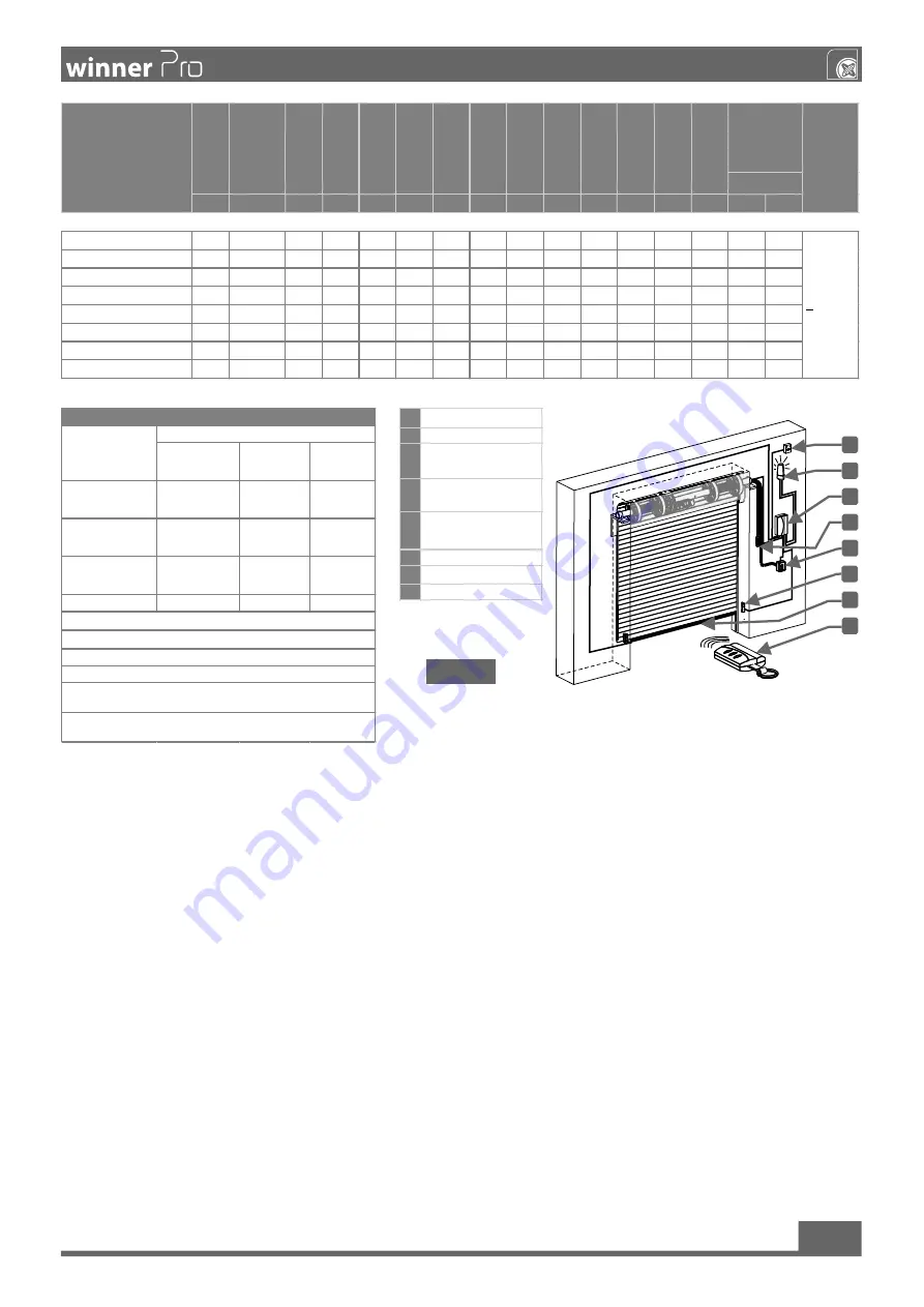
1
Bipolar switch
2
Flashlight
3
Electronic board with
built-in receiver
4
Manual unlocking of the
actuator
5
Key switch 2 and
external brake release.
6
Photocells
7
Security band
8
transmitter
Expert people
(outside a public
area *)
Expert people
(public area)
Unlimited use
In the presence of
someone
A
B
X
With pulses in sight
(eg sensor)
C o E
C o E
CyD,oE
With impulse not in
sight (on remote
control)
C o E
CyD,oE
CyD,oE
Automatic
CyD,oE
CyD,oE
CyD,oE
D
: Sensors to detect obstacles and / or other devices that limit forces
betw een limits of standards EN 12453 - Appendix A.
E
: Photocells placed as indicated in EN 12445 point 7.3.2.2 for the w hole
height of the door up to a maximum of 2.5 m).
USE OF THE CLOSURE
TYPE OF CONTROL
* A typical example is the closures that do not access the public w ay.
A
: Pulsating command w ith dead man ( w ith sustained action),
B
: Key selector w ith dead man.
C
: Regulation pow er motor.
Com ponents to be installed according to EN12453
Kg.
V
HZ
W
A
Nm
Kg.
ºC
ºC
uF
206
220
WPRO V17 400/200 EF
7
220-240V 50/60 400
2,15
105
100
20
10
20
-20
+50
14
7,7
8,4
8,9
WPRO V17 400/200
6
220-240V 50/60 400
2,15
110
105
20
10
20
-20
+50
14
7,7
8,4
8,9
WPRO V17 600/200 EF
7,8
220-240V 50/60 600
2,7
168
160
20
10
20
-20
+50
18
7,7
8,4
8,9
WPRO V17 600/200
6,8
220-240V 50/60 600
2,7
178
170
20
10
20
-20
+50
18
7,7
8,4
8,9
WPRO V17 630/200 EF
8,3
220-240V 50/60 630
2,8
189
180
20
10
20
-20
+50
20
7,7
8,4
8,9
WPRO V17 630/200
7,3
220-240V 50/60 630
2,8
199
190
20
10
20
-20
+50
20
7,7
8,4
8,9
WPRO V17 1260/200 EF
12,9 220-240V 50/60 1260
5,6
357
340
20
10
20
-20
+50
20
7,7
8,4
8,9
WPRO V17 1260/200
11,9 220-240V 50/60 1260
5,6
367
350
20
10
20
-20
+50
20
7,7
8,4
8,9
T.
M
IN
.
TYPE
O
PE
RA
TO
R
W
EI
G
H
T
PO
W
ER
SU
PP
LY
FR
EQ
U
EN
C
Y
PO
W
ER
C
U
RR
EN
T
TO
RQ
U
E
M
A
X,
LI
FT
IN
G
M
A
X,
CY
CL
ES
PE
R
D
A
Y
RP
M
IP
<70dB(A)
T.
M
A
X.
CA
PA
CI
TO
R
LI
M
IT
SW
IT
CH
M
A
X.
PU
LE
Y
TU
RN
S
MAX. HEIGHT
BLIND 10 mm.
N
O
IS
IN
ES
S
PULEY
Fig.20


