


Setup
Page 37 of 87
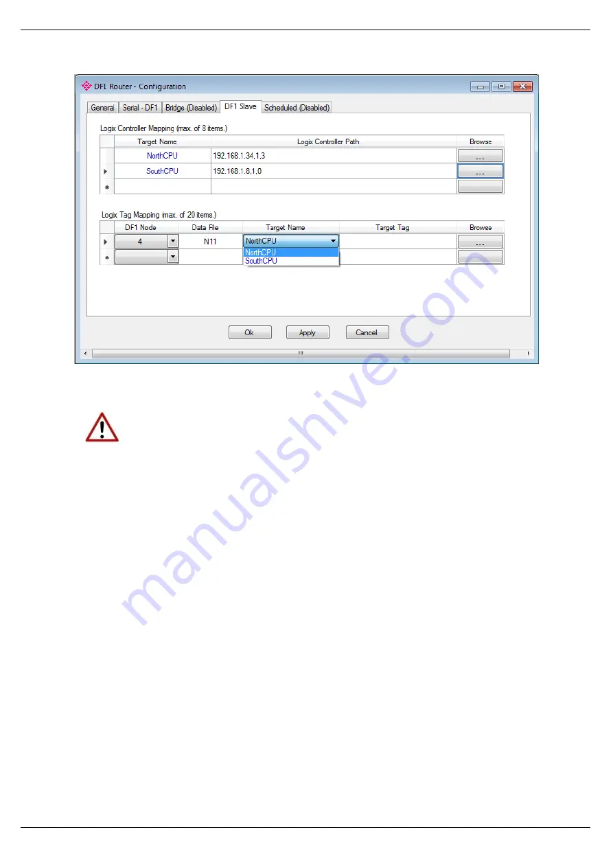
Figure 3.32 – DF1 Slave Mapping (PLC2 Messages)
NOTE: When using Unprotected Bit Write PLC-2 messages only one byte worth
of bits can be written at a time.
The module can emulate more than one destination DF1 Node Address, and thus route
multiple messages to different Logix controllers. For this reason it is important to enter the
correct associate DF1 Node address in each mapping record.
The next column is used to enter the DF1 data file. It is important to enter only the file here
(e.g. N11) and not a data word address (e.g. N11:0). The first element of the entered DF1 file
(e.g. N11:0) will then map to the first element of the Logix array and so on. When using PLC2
messages, type in “PLC2” into the Data File field as shown in figure 3.27.
Below is an example of the target tag selection. The Target Tag can be either entered manually
or selected using the Tag Browser in the PLX50 Configuration Utility. The Tag Browser requires
the controller to be available on the network.
To browse to the tag, click on the Browse button. The Tag Browser opens and scans all the
tags inside that controller. If the controller has been recently scanned in this session, then a
cached version of the tags is displayed. A rescan of the tags can be triggered by selecting the
Refresh button in the Tag Browser’s toolbar.
All non-array tags will be disabled, guiding you to select a suitable tag.


