


Setup
Page 27 of 87
The module can emulate more than one destination DF1 Node Address, and thus route
multiple messages to different Ethernet devices. For this reason it is important to enter the
correct associate DF1 Node address in each mapping record.
When using PCCC data messaging the connection class can be configured by selecting either
Class 3 or Unconnected (UCMM) messaging. This is done by selecting from the Connection
drop-down box in the Bridge tab.
The controller paths can either be entered manually or you can browse to them by clicking
the Browse button. The Target Browser requires the controller to be available on the network.
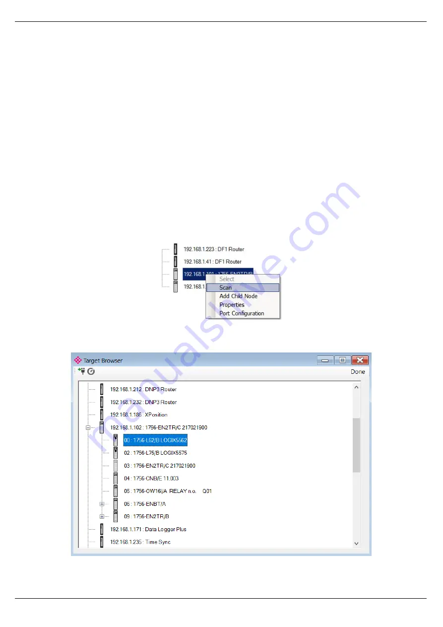
The Target Browser will open and automatically scan for all EtherNet/IP devices.
If the Ethernet/IP module is a bridge module, it can be expanded by right-clicking on the
module and selecting the Scan option.
Figure 3.17. - Scanning node in the Target Browser
Figure 3.18. - Target Browser selection


