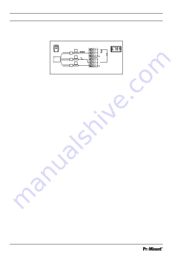
NPN connection information
R
C
P_DFI_0009_SW
3
2
4
+
S
+
S
NPN
*
R
C
*
Fig. 8: Wiring diagram NPN-outputs to indicating instrument or PLC
Rc* Collector resistance or pull-up resistance. For more information, see
Ä
‘Collector resistance
R
C
, minimum level’ on page 24.
Assembly and Installation
20


