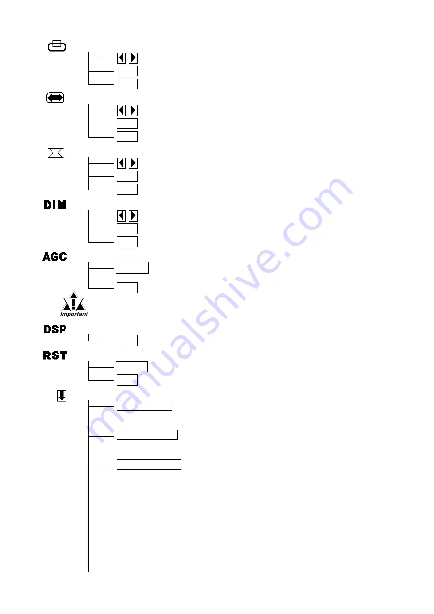
background image

V-POS

Adjustment buttons

  SET

Applies the setting and then returns to the main menu.

  ESC

Cancels the setting and then returns to the main menu.

H-SIZE

Adjustment buttons

  SET

Applies the setting and then returns to the main menu.

  ESC

Cancels the setting and then returns to the main menu.

PHASE

Adjustment buttons

  SET

Applies the setting and then returns to the main menu.

  ESC

Cancels the setting and then returns to the main menu.

BACKLIGHT

Adjustment buttons

AUTO GAIN CONTROL

  SET

Applies the setting and then returns to the main menu.

  ESC

Cancels the setting and then returns to the main menu.

  START

Starts the auto gain control and then automatically returns to the main
menu.

  ESC

Returns to the main menu.

DISPLAY MODE

  ESC

Returns to the main menu.

OSD CLEAR

  START

Clears the setting.

  ESC

Cancels the setting and then returns to the main menu.

SYSTEM

  CLICK TONE

Enables/disables the click sound. With this parameter, the
sound level can also be adjusted.
                         (Default value : OFF <Click sound disabled>)

Select the time period from 1min, 3min, 5min, 10min, and OFF
(Auto OFF function disabled).

  720×400 DSP

When an input data resolution of 720 X 400 is used in the VGA
text mode, set this parameter to ON. For other resolutions, set
this parameter to OFF.                                   (Default : OFF)

  AUTO OFF DSP

Enables/disables the screen display Auto OFF function and
sets the time when the Auto OFF function is enabled.
                        (Default : OFF <Auto OFF function disabled>)
The Auto OFF function automatically turns off the display to
prevent the screen from burning out when the touch panel is
not used for some period of time. With this parameter, you can
set the time interval to turn off the screen display (how much
time passes before the screen display is turned off) when the
touch panel is not used. If the touch panel is not touched over
the set time, the backlight will automatically turns off.

• Be sure to perform the auto gain control when the screen has both 100%

black and 100% white areas displayed.

Summary of Contents for FP2650-T41

Page 1: ...out and touches the panel a potentially dangerous machine operation error can occur Therefore do not use FP unit touch screen switches for the control of equipment safety mechanisms such as Emergency...

Page 2: ...leading to a mal function To prevent excessive heat from building up inside the unit do not install the FP where its ventilation holes may be blocked Also do not install or store the FP near high temp...

Page 3: ...d at least 100 mm away from any adjacent structures or machine parts Iftheseconditionsarenotmet theheatgeneratedbytheFPunit sinternalcomponentsmay cause the unit to fail to meet UL standard Theend use...

Page 4: ...ion to quality How ever should you find anything damaged or missing please contact your local FP distributor immediately Package Contents FP unit CD ROM 1 FP2650 T41 FP2650 T41 Series User Manual Inst...

Page 5: ...st and receiving commands from the host I Front LED Used to indicate power supply backlight or image signal input status Front View Rear View A B I Bottom View C D E F G H The FP2650 T41 unit s PDF ma...

Page 6: ...2 Dimensions FP2650 T41 Unit mm in Front View 301 11 85 227 8 94 243 9 57 317 12 48 58 2 28 Top View 8 0 31 Side View...

Page 7: ...anel data transmission Used to set the touch panel data input command control method to either USB or RS 232C ON USB OFF RS 232C Default setting 1 2 Display hide the OSD Used to display or hide the OS...

Page 8: ...pecified Analog RGB cable is used FP unit operation cannot be guaranteed due to the possibility of noise interference Pin Assignments and Signal Names for Analog RGB Pin No Signal Name Condition Pin L...

Page 9: ...CLOCK SHIELD 11 TMDS DATA1 3 SHIELD 23 TMDS CLOCK 12 NC 24 TMDS CLOCK DVI D Pin Assignments and Signal Names Connector DVI D 24 pin male Connector set screw Inch type 4 40 Cable DVI D Cable FP DV01 5...

Page 10: ...gnal names used for FP unit RS 232C interfaces are designed to match the pin order used on most PC serial connectors which allows a straight cable to be used to connect the two Therefore connect each...

Page 11: ...resistance Be sure to change the gasket periodically or when scratches or dirt become visible Be sure to use gasket model GP570 WP10 MS Be sure the gasket s seam is not inserted into any of the unit s...

Page 12: ...Wiring Installation fastener FP Panel Unit mm in Panel 301 5 11 87 1 0 0 04 0 227 5 8 96 1 0 FP 0 04 0 Panel thickness 1 6mm 0 06in to 10 0mm 0 39in To avoid an electric shock when connecting the FP u...

Page 13: ...nit will result in excess noise and vibration Connecting the AC Power Cord When connecting the power cord be sure to follow the procedures given below 1 Confirm that the FP unit s Power Cord is unplug...

Page 14: ...signal lines When surge indirect lightning stroke etc which corresponds to surge resis tance specifications or more occurs control surge by a surge absorber etc To reduce noise make the power cord as...

Page 15: ...settings such as activating the click sound ESCAPE Cancels the setting and returns to the upper level In the main menu this command closes the OSD Item 1 When using DVI D the message DO NOT NEED SETU...

Page 16: ...els the setting and then returns to the main menu H POS SET Applies the setting and then returns to the main menu Adjustment buttons ESC Cancels the setting and then returns to the sub contrast adjust...

Page 17: ...ables the click sound With this parameter the sound level can also be adjusted Default value OFF Click sound disabled Select the time period from 1min 3min 5min 10min and OFF Auto OFF function disable...

Page 18: ...SET button applies the set value and enables the setting The set value won t be canceled unless the power is turned OFF or the value is reset If the power is turned OFF without saving the set value th...

Page 19: ...f a different model backlight may cause a FP malfunction or breakdown FP Model No Backlight Model No FP2650 T41 CA5 BLU12XGA 01 Digital Electronics Corporation 8 2 52 Nanko Higashi Suminoe ku Osaka 55...

Reviews: