page 17
C
O
M
M
E
R
C
I
A
L
P
R
O
D
U
C
T
S
D
I
V
I
S
I
O
N
20.
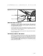
Tighten all mounting screws with a 9/16" wrench.
Once you have tight-
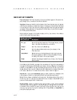
ened the eight bolts that attach the frame stabilizers to the base frame (refer
to Diagram 10), proceed with tightening the four bolts installed in each of the
two upright support brackets. See Diagram 11. Once the stabilizers are se-
cured, tighten the two bolts that secure the upright support to the base frame
(refer to Diagram 6, #2).
Diagram 11
Tighten the
mounting bolts.
Upright support
bracket
Frame stabilizer
Bolts (F) and
washers (G)
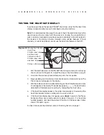
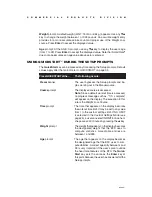
Diagram 12
Remove the cover
fasteners.
Upright support
bracket
Remove a screw
from each side.
2
1
21.
Remove the cover fasteners from the EFX.
Diagram 12. Use a Phillips-
head screwdriver to remove:
• two screws, one on each side of the upright bracket support. Set the
screws aside for use in step 27, c.
• four screws, two on each side of the base tube near the lift motor. Set the
screws aside for use in step 23, d.
• two screws from the base of the upright bracket support. Note the size of the
screw closest to the ramp. It is 3/4-inches in length. Refer to Diagram 13.
Remove two screws
from each side of the
base tube.
Remove two screws
from the base of the
bracket.


