35
User Manual
neuro 100 96X96
Output 1 B & C
Jumper Settings
Input
Jumper Setting
Output 2
Jumper Setting
1 2
3
C
1
3
2
4
B
1 2
3
A
1 2
D
Display
Keys
3
1 2
3
E
CPU Board
}
Mounting Output Modules
Mounting / Un-Mountion of Modules
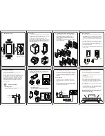
The Figure 2.4 Illustrates how to mount output-2 & output-3 module, respectively. Notice the orientation of the controller & a
few identifying components shown in figure to help locate the plugs for the modules.
Figure 2.4
The plug for the Serial Communication or Remote Alarm Acknowledgment module is located on the Power-supply PCB. The
Figure 2.5 below illustrates how to plug-in the Serial Communication/Remote Alarm Acknowledgment module. To plug (or
unplug) the module simply insert (or remove) the socket into (or from) the plug.
Figure 2.5
Mounting Serial Communication Module
Output 3
Jumper Setting
Serial Communication
Module
Power-Supply
PCB
8 Pin Male Plug
8 Pin Female
Socket
CN3
CN4
1 2
3
A
1 2
3
B
neuro 100
PPI


