24
User Manual
neuro 100
PANEL MOUNTING
Follow the steps below for mounting the Indicator on panel:
1.
Prepare a square cutout to the size shown in Figure 10.2.
2.
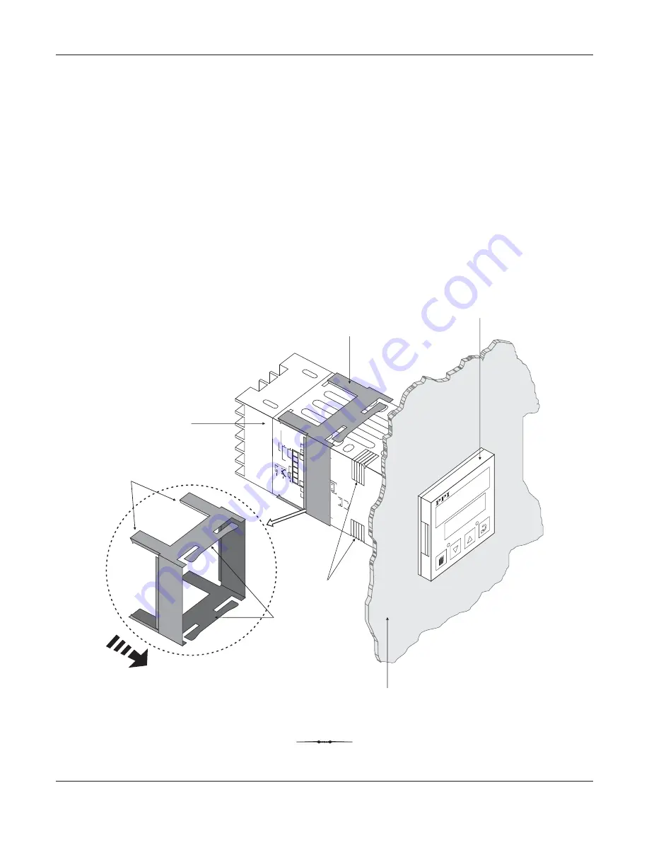
Remove the Panel Mounting Clamp from the Indicator Enclosure.
3.
Insert the rear of the Indicator housing through the panel cutout from the front of the mounting panel.
4.
Hold the Indicator gently against the mounting panel such that it positions squarely against the panel wall, see Figure 10.3.
Apply pressure only on the bezel and not on the front label.
5.
Slide the mounting clamp forward until it is firmly in contact with the rear face of the mounting panel and the tongues of the
clamp engage in the ratchets on the Indicator enclosure, as shown in Figure 10.3. Ensure that the springs of the clamp
push firmly against the rear face of the mounting panel for secured mounting.
Figure 10.3
UP
UP
PPI
OP1
OP2
HBA
Panel Mounting Clamp
Mounting Panel with
Square Cutout
indicator
Tongues
Springs
Ratchets
Bezel
Slide Forward
neuro 100
neuro
1
2
3
4
5
6
7
8
9
10
11
12
13
14
15
16
17
18
N/O
C
+
-
R
EL
AY
SS
R
/ D
C
Li
ne
ar
O
UT
PU
T
1
Pt100
T/C
mV
, V
, mA
INP
UT
OUT
PUT
2
+
SSR
/ DC
Line
ar
REL
AY
N/O
N/C
C
OUT
PUT
3
SERIAL
COMMS.
+
SSR / DC Linear
RELA
Y
N/O
N/C
C
PPI
L
N
AC
DC
SU
PP
LY
GND
A
B
AUXILIAR
Y SP
SELECTION


