


POWERTRONIX SpA reserves the right to modify this document without any notice
Pag. 38 di 41
R&D – PROCEDURA START-UP DT 0419 – E02
5
UPS IN PARALLEL
5.1
SYSTEM SET-UP
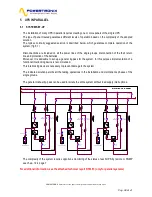
The installation of many UPS in parallel requires creating one or more panels of the single UPS.
The type of panel created guarantees different levels of operation based on the complexity of the adopted
solution.
The typical, normally suggested solution is described below, which guarantee complete operation of the
system. (fig.5.1)
Disconnections are included on all the power lines of the single groups, disconnection of the their return
line and protection of the batteries.
Moreover, it is advisable to set-up a general by-pass for the system, for this purpose implementation of a
functional interlocking device is recommended.
This interlocking device is necessary to prevent damage to the system
The indicated solution permits all the testing operations in the installation and maintenance phases of the
single groups.
The general manual by-pass can be used to isolate the entire system without load supply interruptions.
Load
Standard mains
Standard reserve
BY-PASS
I
BATTERY1
IU1-4
OUT
IU1-1
INPUT
BT1
BATTERY CABINET
IU1-2
RESERVE
IU1-3
BY-PASS
IU2-1
INPUT
IU2-2
RESERVE
IU2-3
BY-PASS
BT2
BATTERY CABINET
IU2-4
OUT
I
BATTERY2
I
BATTERY2
IU2-3
BY-PASS
IU2-1
INPUT
IU2-2
RESERVE
IU2-4
OUT
BT2
BATTERY CABINET
DISTRIBUTI ON PANEL
=
UPS1
R
E
S
E
R
V
E
L
IN
E
=
=
R
E
S
E
R
V
E
L
IN
E
UPS2
=
R
E
S
E
R
V
E
L
IN
E
UPS..N
=
=
The complexity of the system requires opportune monitoring of the status of each UPS by remote or SNMP
see chap. 1.2.4 page 7
For additional information, see the attached technical report DT0367. (only for parallel systems)


