


POWERTRONIX SpA reserves the right to modify this document without any notice
Pag. 14 di 41
R&D – PROCEDURA START-UP DT 0419 – E02
2.6
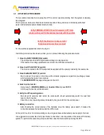
CONNECTIONS AND LAYOUT TO THE MAINS
For connection to the mains a layout solution like the one shown in diagram 2.6 is recommended. The
circuit breakers B-C-D are magnetothermic type without differential protection, or if this is required, with a
triggering current greater than 0.3A, delayed and suitable for load with DC current (type A).
Switch A is used as external BY-PASS.
Load
Standard mains
Standard mains
Standard reserve
Standard reserve
BT1
BATTERY CABINET
I
BATTERY1
I1
INPUT
I2
RESERVE
I3
BY-PASS
I4
OUT
C
D
B
BY-PASS
=
=
RESERVE LINE
UPS
D
IS
T
R
IB
U
T
IO
N
P
A
N
E
L
fig. 2.6
A


