


POWERTRONIX SpA reserves the right to modify this document without any notice
Pag. 22 di 41
R&D – PROCEDURA START-UP DT 0419 – E02
Tab 3.1a
STATUS
UPS OK
Alarm present
Alarm stopped
GREEN LED
ON*
OFF
ON
RED LED
OFF
ON
OFF
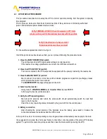
On the control panel of master UPS in the parallel system, for its identification as a master, the normal
operation is indicated by flashing green LED.
3.2
LCD CONTROL PANEL
During normal UPS operation the control panel presents the series of messages to indicate the operating
status of the components of the system, therefore the operator is informed in real time (also with sound
signal) about any faults occurred in the system.
Table 3.1b summarizes the list of available menus.
MENU
N°
NOTES
COMMAND MODE
1
Inverter switch on and off, static switch, battery test
EVENTS HISTORY
2
Displays the log of events and alarms
OPERATING LANGUAGE
3
Enables the change of interface language
CLOCK
4
Date and time settings
UPS CONFIGURATION
5
Measurements adjustments and relays board test
Table 3.1b
Fig. 3-1b LCD panel picture
MENU PUSH BUTTON
To return to the previous
menu or to enter into
main menu from the
alarm display
allarmi
BACK PUSH BUTTON NEXT PUSH BUTTON
To scroll among the menu and the sub menu.
Pressing them both at the same indicates
ENTER command
- - - - - - - - - - - - - - - - - - - - - - - - - - - - - - - -
Measurements scrolling
ESC PUSH BUTTON
To switch off
the buzzer
- - - - - - - - - - - - - - - -
Events log scrolling
- - - - - - - - - - - - - - - -
Return to the previous
menu


