


POWERTRONIX SpA reserves the right to modify this document without any notice
Pag. 27 di 41
R&D – PROCEDURA START-UP DT 0419 – E02
4
INSTRUCTIONS FOR THE UPS
4.1
INTRODUCTION
This chapter describes how to correctly use the system.
The UPS may be in one of the following operating conditions:
•
Normal operation
- The load is supplied by the UPS.
The UPS is in normal operation and uses mains voltage to supply energy to the load and charge the
batteries.
This mode guarantees complete uninterrupted power passed to the load.
•
Operation with internal automatic by-pass
- The load is supplied by the mains.
In the event of an inverter fault and/or overload, the power to the load is provided by the reserve line.
This mode does not guarantee complete uninterrupted power passed to the load.
•
Operation with maintenance manual by-pass enabled
- The UPS is disabled.
The load is connected directly to the mains through the maintenance or emergency manual
by-pass line.
This mode does not guarantee complete uninterrupted power passed to the load.
•
Battery operation
- The load is supplied by the UPS.
The UPS is in normal operation and uses the battery energy to supply the load due the mains voltage
absence.
This mode guarantees complete uninterrupted power passed to the load.
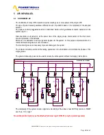
4.2
POWER SWITCHES
The system maintenance elements are located behind the front doors, installed horizontally and described
in order from left to right side (refer to the fig. 4.3):
MAINS INPUT SWITCH (I1):
connects the UPS to the mains voltage.
RESERVE INPUT SWITCH (I2):
connects the UPS to the reserve line voltage.
MANUAL BYPASS SWITCH (I3):
allows disconnecting the entire UPS and providing mains supply to
the load. This switch is protected with the small padlock to avoid accidental use.
UPS OUTPUT SWITCH (l4):
connects the UPS to the load.
Above has been described UPS switches. There are also battery breakers,
placed inside battery module
and in every external battery module
To completely isolate the unit from hazardous voltages it is necessary
to open also the battery switch, which is not present on the UPS.
Also remember about the presence of potentially charged capacitors inside the converter
It means that you must wait for at least 10 min. before accessing to the internal parts of the UPS.


