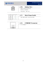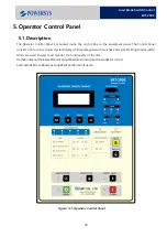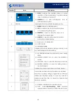
26
Load Break Switch Control
ERT-200S
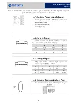
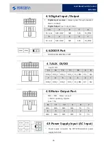
4.5.
Digital Input /Output
•
Digital Input receives
2 status signals through insulated
electric contacts.
•
Digital Output
has 2 output relays.
10
9
8
7
6
M. Lock
GAS LOW
52B
52A
DI_COM
5
4
3
2
1
M. Lock
GAS LOW
52B
52A
DI_COM
4.6.
DOOR Port
-
DOOR OPEN SENSING PORT
4.7.
AUX. DI/DO
-
Aux DI DO
14
13
12
11
10
9
8
DO4_2 DO3_2 DO2_2 DO1_2 DI_COM DI3
DI4
7
6
5
4
3
2
1
DO4_1 DO3_1 DO2_1 DO1_1 DI_COM DI1
DI2
4.8.
Motor Output Port
-
MO+ / MO- : Motor connect
->Motor operating Signals.
-
Fuse : 15A
12
11
10
9
8
7
MO+
MO+
MO-
MO-
TC-
TC-
6
5
4
3
2
1
MO+
MO+
MO-
MO-
TC-
TC-
4.9.
Power Supply Input (AC Input)
-
Power supply connecter has ERT-200Soperation power
supply terminal.
Summary of Contents for ERT-200S
Page 1: ...Feeder Remote terminal Unit ERT 200S Manual www powersys kr...
Page 13: ...13 Load Break Switch Control ERT 200S 2 5 Function BlockDiagram...
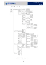
Page 38: ...38 Load Break Switch Control ERT 200S 5 3 3 Menu structure tree Figure Menu Tree Structure...
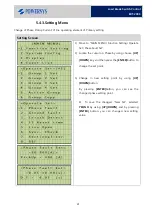
Page 42: ...42 Load Break Switch Control ERT 200S...
Page 96: ...Appendix 1 Drawings 1 Enclosure Control Cabinet...


